
Related Manuals for WERTHER INTERNATIONAL TITANIUM BIKE


Summary of Contents for WERTHER INTERNATIONAL TITANIUM BIKE
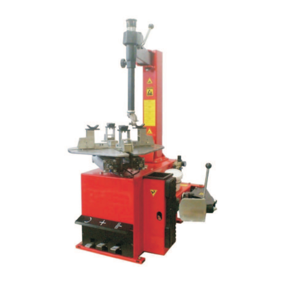
- Page 1 TITANIUM BIKE N/13 SMONTAGOMME SEMIAUTOMATICO SEMI AUTOMATIC TYRE CHANGER DÉMONTE-PNEUS SEMI-AUTOMATIQUE AUTOMATISCHE REIFENMONTIER DESMONTADORA DE NEUMÁTICOS SEMIAUTOMÁTICA...
- Page 3 Halbautomatische Reifenmontiermaschine mit Schwenkarm für Motorräder, Gokart und ATVReifen von 4” bis 23”. Desmontadora de neumáticos semiautomática con brazo a bandera, para ruedas de moto y motocicletas, karts y ruedas ATV de 4” a 23”. Modello -Model- Modèle -Model- Modelo: TITANIUM BIKE COSTRUTTORE:-MANUFACTURER:-FABRICANT:-HERSTELLER:-FABRICANTE WERTHER INTERNATIONAL S.p.A.
- Page 4 PRINTING CHARACTERS AND SYMBOLS Throughout this manual, the following symbols and printing characters are used to facilitate reading: Indicates the operations which need proper care Indicates prohibition Indicates a possibility of danger for the operators BOLD TYPE Important information 2 / 24 REV.
-
Page 5: Table Of Contents
CONTENTS INTRODUCTION GENERAL INFORMATION TRANSPORT, UNPACKING AND STORAGE INSTALLATION OPERATION INFLATING MAINTENANCE TROUBLESHOOTING ELECTRIC AND PNEUMATIC DIAGRAM 3 / 24 REV. 01 2013... -
Page 6: Introduction
CHAPTER 1 – INTRODUCTION INTRODUCTION Thank you for purchasing a product from the line of tire changers. The machine has been manufactured in accordance with the very best quality principles. Follow the simple instructions provided in this manual to ensure the correct operation and long life of the machine. Read the entire manual thoroughly and make sure you understand it. - Page 7 Any tampering or modification to the equipment carried out without the manufacturer’s prior authorization will free him from all responsibility for damage caused directly or indirectly by the above actions. Removing or tampering with safety devices immediately invalidates the guarantee. The tire changer comes complete with instruction and warning transfers which are designed to be long-lasting.
-
Page 8: General Information
CHAPTER 2 – GENERAL INFORMATION INTENDED USE This tire changer has been designed and manufactured exclusively for removing and mounting motorcycle tires from/onto rims from 3.6" to 22" and a maximum diameter of 1000 mm. particular THE MANUFACTURER cannot be held responsible for any damage caused through the use of this tire changer for purposes other than those specified in this manual, and therefore inappropriate, incorrect and unreasonable. - Page 9 DANGER WARNING SIGNS Fig . 2 7 / 24 REV. 01 2013...
- Page 10 TECHNICAL SPECIFICATION 3.6” – 14” External locking rim dimension 10” – 20” Max. tire diameter 1000mm (39”) Max tire width 270mm (10”) Force on bead breaker blade (10 bar) 3000 kg Working pressure 10 bar (145 psi) Inflating pressure device max. 3.5 bar (50 psi) 220V/380V 230V/400V 3 Ph Power supply voltage...
-
Page 11: Transport, Unpacking And Storage
CHAPTER 3 – TRANSPORTATION, UNPACKING AND STORAGE TRANSPORTATION The tire changer must be transported in its original packaging and kept in the position shown on the package itself. The packaged machine may be moved by means of a fork lift truck of suitable capacity. Insert the forks at the points shown in figure 3. -
Page 12: Installation
CHAPTER 4 – INSTALLATION 4.1 SPACE REQUIRED When choosing the place of installation be sure that it complies with current safety at work regulations. The tire changer must be connected to the main electric power supply and the compressed air system. - Page 13 POSITIONING AND PARTS ASSEMBLY 4.2.1 Arm assembly Unscrew the pallet fixing screws and set the tire changer on the floor. Unscrew the 4 screws from the body, set the vertical arm into the proper seat and fix the screw again (Fig. 5/a). Make sure the horizontal arm is on the vertical arm’s support and the pin is locked with nuts and washers as shown in Fig.
- Page 14 12 / 24 REV. 01 2013...
- Page 15 COMMISSIONING Any electric connection job must be carried out by professionally qualified personnel. Make sure that the power supply is right. Make sure the connection of the phases is right. Improper electrical hook-up can damage motor and will not be covered under warranty. Check to make sure the characteristics of your systems correspond to those required by the machine.
- Page 16 TURNTABLE LOCKING VALUE ADJUSTING The tire changer turntable is preset by the manufacturer on a range measure from 3.6” to 14” ext. (clamping the rim outer side). It is however possible to change this dimension range from 10” to 22” ext.
-
Page 17: Operation
CHAPTER 5 – OPERATION Do not use the machine until you have read and understood the entire manual and the warning provided. Before carrying out any operation, deflate the tire and take off all the wheel balancing weights. The operation of the tire changer is divided into three parts: a) BREAKING THE BEAD b) REMOVING THE TIRE c) MOUNTING THE TIRE... - Page 18 REMOVING THE TIRE Before any operation make sure to remove the old wheel balancing weights and check that the tire is deflated. During arm tilting make sure that nobody stats behind the tire changer. Spread the supplied grease (or grease of a similar type) onto the tire bead. Failure to use the grease could cause serious damage to the tire bead.
- Page 19 Chains, bracelets, loose clothing or foreign objects in the vicinity of the moving parts can represent a danger for the operator. Fig. 9 MOUNTING THE TIRE It is utmost important to check the tire and rim to prevent tire explosion during the inflating operations.
- Page 20 Move the tire so that the bead passes below the front section of the mounting head and is brought up against the edge of the rear section of the mounting head itself. Keeping the tire bead pressed down into the wheel rim channel with your hands, press down on the pedal (Z) to rotate the turntable clockwise.
-
Page 21: Inflating
CHAPTER 6 – INFLATING The greatest attention is called for when inflating the tires. Keep strictly to the following instructions since the tire changer is NOT designed and built to protect (or anyone else in the vicinity of the machine) if the tire bursts accidentally. -
Page 22: Maintenance
CHAPTER 7 – MAINTENANCE 7.1 GENERAL WARNINGS Unauthorized personnel may not carry out maintenance work. Regular maintenance as described in the manual is essential for correct operation and long lifetime of the tire changer. If maintenance is not carried out regularly, the operation and reliability of the machine may be compromised, thus placing the operator and anyone else in the vicinity at risk. - Page 23 If necessary to adjust the vertical arm locking plate because the tool does not lock or it does not rise from the rim of 2mm necessary for working, adjust nuts as shown in Fig. 17. For cleaning or replacing the silencer for opening/closing clamps, see Fig 18 and proceed as follows: 1.
-
Page 24: Troubleshooting
CHAPTER 8 – TROUBLE-SHOOTING ROUBLE OSSIBLE AUSE OLUTION Turntable rotates only in Reverser broken Replace reverser one direction. Belt broken Replace Reverser broken Replace reverser Turntable does not rotate. Check for loose wire in the motor, plug or socket. Problem with motor Replace motor Adjust the belt tension (chap. -
Page 25: Electric And Pneumatic Diagram
CHAPTER 9 – ELECTRIC AND PNEUAMTIC DIAGRAM 110V/220V/230V – 1PH 220V/230V/380V/400V – 3PH (SINGLE SPEED) 23 / 24 REV. 01 2013... - Page 26 STANDARD PNEUMATIC SYSTEM DIAGRAM 24 / 24 REV. 01 2013...
- Page 28 ED. 04/13 TAV.1.1 BODY 2 / 22 REV. 01 2013...
- Page 29 ED. 04/13 TAV.1.1 BODY ITEM PART NUMBER DESCRIPTION REMARK YC1-3001800 Side cover 106B-2401001 Shell 202W-3018260 Cover 0202067 Screw M10X85 - GB/T70.1 0204005 Self-locking nut M10 - GB/T889.1 0511063 Grease brush YC1-4299984 Grease cup YC1-3000069 Spring YC1-3002102 Wheel support 0202033 Screw M6X20 - GB/T70.1 YC1-3002099 Plastic foot YC1-3006970...
- Page 30 ED. 04/13 TAV.2.1 HORIZ. AND VERT. ARMS 4 / 22 REV. 01 2013...
- Page 31 ED. 04/13 TAV.2.1 HORIZ. AND VERT. ARMS ITEM PART NUMBER DESCRIPTION REMARK 102-2400400 Vertical post YC1-3015565 Pivot YC1-2415589A Horizontal arm YC1-3012632 Rubber spacer YC1-3012631 Arm frame 0204005 Self-locking nut M10 - GB/T889.1 0204012 Nut M10 - GB/T6172.1 YC1-3005407 Spring YC1-3001759 Arm knob 0202049 Screw M8X30 - GB/T70.1...
- Page 32 ED. 04/13 TAV.2.1 HORIZ. AND VERT. ARMS YC1-3007352 Washer YC1-2004002 Hand wheel YC1-3012978 Inflator hook 0203004 Nut M6 - GB52 YC1-3007801-A M/C mounting tool 0209033 Screw M10X10 - GB/T80 YC1-3009018 Special screw YC1-3000215 Peak roll YC1-3006689 Plastic insert 0209044 Screw M10X12 - GB/T80 6 / 22 REV.
- Page 33 ED. 04/13 TAV.3.1 PEDAL BOX 7 / 22 REV. 01 2013...
- Page 34 ED. 04/13 TAV.3.1 PEDAL BOX ITEM PART NUMBER DESCRIPTION REMARK 0201026 Screw M8X16 - GB/T5783 0205008 Washer D.8 - GB/T97.1 YC1-3002157 Pedal A 0205013 Washer D.12 - GB/T97.1 YC1-3007953 Bush YC1-3000142 Pedal control spring YC1-3002159 Pedal B YC1-3003094 Pedal alignment pin YC1-3002161 Pedal box base 0212001...
- Page 35 ED. 04/13 TAV.3.1 PEDAL BOX 0306097 Rilsan hose 8X5 L=70 0306033 90° rotation union 8-1/8 YC1-3002442 Valve pin 1 0204004 Self-locking nut M8GB/T889. YC1-3013333 Pedal return spring 0201016 Screw M6X50 - GB/T5782 YC1-4299912 Connection rod 0215019 Curved spring washer D.8 - GB/T860 0202033 Screw M6X20 - GB/T70.1 0205006...
- Page 36 ED. 04/13 TAV.3.1 PEDAL BOX YC1-3015340 Reverser support Nut M6 GB52 0203004 YC1-3015342 Support YC1-2005000 Pedal control unit YC1-2006297 Bead breaker valve unit YC1-2002529 Turntable valve unit 10 / 22 REV. 01 2013...
- Page 37 ED. 04/13 TAV.4.1 BEAD BREAKER 11 / 22 REV. 01 2013...
- Page 38 ED. 04/13 TAV.4.1 BEAD BREAKER ITEM PART NUMBER DESCRIPTION REMARK 0203022 Nut M18X1.5 - GB/T6171 0309084 O-ring 16X2.65 C207010008 Seal support ring C207010004 Seal 188X200X12 C207010001 Guiding ring C207010002 Piston 0305041 Guiding ring 67X9.5X2 0606004 O-ring 20X2.75 0606016 Scraper 20X30X7 YC1-4398146 Washer 0211004...
- Page 39 ED. 04/13 TAV.4.1 BEAD BREAKER YC1-3000114A Arm spring 0201099 Screw M16X90 - GB/T5782 0204008 Self-locking nut M16 - GB/T889.1 0204009 Self-locking nut M18 - GB/T889.1 0204005 Self-locking nut M10 - GB/T889.1 0202057 Screw M10X70 - GB/T70.1 YC1-2415574 Bead breaker arm YC1-3008990 Pivot pin 0204013...
- Page 40 TAV.5.1 SELF CENTERING TURNTABLE ED. 04/13 14 / 22 REV. 01 2013...
- Page 41 TAV.5.1 SELF CENTERING TURNTABLE ED. 04/13 ITEM PART NUMBER DESCRIPTION REMARK YC1-2112865 Turntable YC1-2016001 Turntable flange unit YC1-3006869-A Connection rod spacer 0212011 Seeger D.65 - GB/T894.1 YC1-2008060 Turntable cylinder 0204007 Self-locking nut M12 - GB/T889.1 0205013 Washer D.12 - GB/T97.1 YC1-4198856 Piston YC1-3002901...
- Page 42 ED. 04/13 TAV.5.1 SELF CENTERING TURNTABLE YC1-3006879 Spacer 0201100 Screw M16X1.5X40 - GB/T5786 YC1-3000062 Turntable cap YC1-3009778 Washer 102-2415755 Slide guide 102-3006257 YC1-3015169 Turntable plate 102-3080002 Support 0202063 Screw M10X35 - GB/T70.1 102-2080100 M/C clamp unit 0202047 Screw M8X25 - GB/T70.1 102-3080100 Flip clamp YCF1-3005070...
- Page 43 ED. 04/13 TAV.5.1 SELF CENTERING TURNTABLE YC1-3007420 Bush 0201011 Screw M6X12 - GB/T5783/ YC1-3006870 Connection plate YC1-3006878 0203004 Nut M6 - GB52 YC1-3015187 Rivet 17 / 22 REV. 01 2013...
- Page 44 ED. 04/13 TAV.6.0 MOTOR – REDUCTION GEAR GROUP 18 / 22 REV. 01 2013...
- Page 45 ED. 04/13 TAV.6.0 MOTOR – REDUCTION GEAR GROUP ITEM PART NUMBER DESCRIPTION REMARK 0201069 Screw M10X55 - GB/T5780 0205011 Washer D.10 - GB/T97.1 YC1-3010872 Top gear box 0202049 Screw M8X30 - GB/T70.1 0213011 Elastic pin 8X20- GB/T119.1 0214006 Bearing 6212-2RS - GB/T276 YC1-3199596 Gear box pulley 0204013...
- Page 46 ED. 04/13 TAV.6.0 MOTOR – REDUCTION GEAR GROUP 0203009 Nut M10 - GB52 0201050 Screw M10X35 - GB/T5783 YC1-3000164 Spherical washer 0509065 1PH motor 230V 0.75KW 0509053 3PH motor 230V/400V 0.55KW 0203029 Nut M8 - GB/T6170 0205008 Washer D.8 - GB/T97.1 0201062 Screw M10X20 - GB/T5783 YC1-3000149A...
- Page 47 ED. 04/13 TAV.8.1 AIR LUBRICATOR GROUP 21 / 22 REV. 01 2013...
- Page 48 ED. 04/13 TAV.8.1 AIR LUBRICATOR GROUP ITEM PART NUMBER DESCRIPTION REMARK YC2-2010781-1 Safety valve unit 3.5bar 0306037 90° quick union 8-1/4 0205013 Washer D.12 - GB/T97.1 0307039 Pressure regulator 3.5bar 0305014 Plug 1/8 0306106 Pressure relief valve 1/8 5.5bar 0306144 Quick union 8-1/4 0306011 Inflator...
- Page 49 Dichiarazione di conformità - Déclaration de conformité Declaration of Conformity - Konformitätserklärung Declaración de conformidad - Overensstemmelseserklæring Överensstämmande intyg - EG-Conformiteitsverklaring WERTHER INTERNATIONAL S.p.A. Via F.Brunelleschi, 12 42124 CADE’ (Reggio Emilia) Italy Tel.++/+522/9431 (r.a.) Fax ++/+522/941997 dichiariamo che lo smontagomme modello declara, que la desmontadora de neumáticos modelo...
Need help?
Do you have a question about the TITANIUM BIKE and is the answer not in the manual?
Questions and answers