
Related Manuals for BLACKHAWK! STL3500

Summary of Contents for BLACKHAWK! STL3500
- Page 1 INSSTL3500GB REV: 06.06.17 3T5 SCISSOR LIFT STL3500 INSTRUCTION MANUAL (Original instructions)
- Page 2 STL3500 Index No Page WARNINGS – SAFETY INSTRUCTIONS INTRODUCTION III) PACKING, TRANSPORT AND STORAGE GENERAL DESCRIPTION TECHNICAL SPECIFICATIONS 10-12 INSTALLATION 13-17 VII) OPERATION VIII) MAINTENANCE TROUBLESHOOTING SPARE PARTS 21-27 FOUNDATION DIAGRAM XII) EC DECLARATION OF CONFORMITY XIII) INITIAL TEST 30-31...
-
Page 3: Warnings - Safety Instructions
STL3500 I) WARNINGS – SAFETY INSTRUCTIONS The manufacturer hereby refuses to accept any responsibility for injury to persons or damage to equipment or property if it appears that incorrect handling of the lift has occurred. This instructions manual only describes the operating and safety aspects which are necessary to the people who are using and installing the equipment. -
Page 4: General Precautions
STL3500 USE THE LIFT ONLY IF ALL THE SAFETY DEVICES ARE WORKING PROPERLY. IF THESE RULES ARE NOT FOLLOWED, SERIOUS INJURY COULD BE CAUSED TO PEOPLE AS WELL AS IRREPARABLE DAMAGE TO THE LIFT AND THE VEHICLE ON THE LIFT. -
Page 5: Safety Devices
STL3500 SAFETY DEVICES The following safety devices have been installed to prevent overloading and damage. A hydraulic protection (parachute valve) prevents descending in case of hose fracture. Thermal protection switches the power off in case of overloading. Overpressure relief valve offers protection against damage due to excessive lifting. -
Page 6: Risk Of Electrocution
STL3500 RISK FOR THE OPERATOR (Figure 4) This risk arises in cases when the operator is not standing at the right place by the pump. When the lift with the vehicle is being lowered, the operator MUST NOT stand below the descending system. -
Page 7: Packing, Transport And Storage
The manufacturer cannot be held responsible for damages to persons, vehicles or objects caused by improper use of the lift. The lift model STL3500 has been designed and built according to: -European Directives 2006/42/CE... -
Page 8: Packing Removal
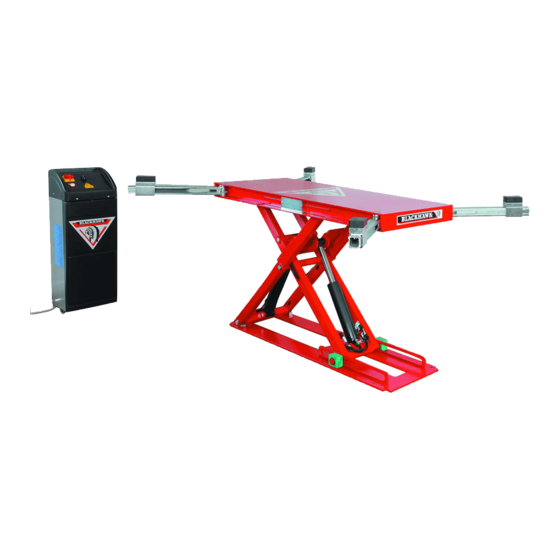
STL3500 TRANSPORT The packages described on page 7 can be lifted and transported using forklifts, cranes or other lifting systems of adequate capacity. Upon receiving goods, verify that no damage has been caused and that there are all parts indicated on the checklist. - Page 9 STL3500 MAIN CONTROL PANEL PMPLIFT Figure 9 MAIN SWITCH LIFTING PUSH BUTTON LOWERING PUSH BUTTON EMERGENCY PUSH BUTTON POWER LED Main switch: The switch can be padlocked to prevent the use of the lift during the maintenance. Lifting push button: When pressed, motor and lifting mechanism are operated.
-
Page 10: Technical Specifications
Limit switch Low voltage controls (24V) The STL3500 has been designed and built for lifting cars of weight not exceeding 3500kg and in closed areas. It must not be used for any other purpose, in particular: washing hoisting... - Page 11 STL3500 CE APPROVAL: approval number assigned to this product is 75.16.130.07 dated May 2017. MANUFACTURER: BLACKHAWK SAS RUE DU RHEINFELD 67100 STRASBOURG FRANCE IDENTIFICATION AND CE LABEL PLATE: Figure 10 The information given on the identification plate is necessary for any assistance or spare parts required.
- Page 12 STL3500 THE WEIGHT OF THE VEHICLE The lift can be used with nearly any vehicle provided that the maximum loading capacity (3500kg) is not exceeded. Check the weight of the vehicles that are loaded. The “DANGER AREA” (Figure 12) is to some extent determined by the dimensions of the vehicle to be lifted.
-
Page 13: Installation Procedure
STL3500 VI) INSTALLATION The lift must be installed taking into account the dimensions of the vehicles to be lifted, and the specified distances from the walls, columns, other machinery, etc. The room must be at least 4500mm in height. The minimum distance from the... - Page 14 STL3500 Figure 13 3. Hydraulic connections Open the front panel of the control unit, remove (pull) the oil tank cap and using a funnel pour in 5 litres of index 32 viscosity hydraulic oil. (BLACKHAWK® Part Number for 5 Litres: LX22Y)
- Page 15 STL3500 4. Electrical diagram MAIN SWITCH MOTOR THERMAL PROTECTION CONTACTOR ELECTROVALVE – AIR CONTROL MOTOR 3 PHASES LOWER LIMIT SWITCH LIGHT RELAY EMERGENCY STOP BUZZER FUSE 2A ELECTROVALVE - DESCENT TRANSFO. 3PH - 230 / 400 - 24V LIMIT SWITCH...
- Page 16 5. Electronic card diagram MAIN SWITCH MOTOR 3 PHASES MOTOR THERMAL PROTECTION LIGHT BUZZER SOUND SIGNAL LIMIT SWITCH ELECTROVALVE - DESCENT ELECTROVALVE – AIR CONTROL EMERGENCY STOP UPPER LIMIT SWITCH LOWER LIMIT SWITCH DANGER Do not for any reason alter the adjustment of the pressure limiter. The mechanical components are not designed to work at a higher pressure.
- Page 17 STL3500 6. Fixing of lift Using a concrete drill, bore 6 holes of 16mm diameter and 120mm depth in the floor. Use the lift frame as a template. Clean the holes and with the help of a hammer, insert the supplied expansive bolts in the floor.
-
Page 18: Operation
STL3500 VII) OPERATION Before installing or removing of the vehicle from the lift, make sure the lift is completely down. Position the vehicle very slowly on the lift making sure that the vehicle is well centred on the platform. LIFTING: 1) Turn the main switch (1) to the position “1”. -
Page 19: Maintenance
STL3500 VIII) MAINTENANCE WARNING Only authorised personnel must carry out maintenance. During maintenance operations it is important to follow the instructions in the chapter “safety” and ensure that all steps are taken to avoid accidental starting of lift. Periodic maintenance: In order to keep the lift in peak condition, it is important to carry out periodic maintenance. -
Page 20: Troubleshooting
STL3500 IX) TROUBLESHOOTING WARNING It is important to follow all precautions in the chapter on “safety” when identifying and searching for faults and carrying out subsequent repairs. Problem Cause Solution The lift does not rise when the lifting The fuse is burnt out Replace the fuse button is pressed. -
Page 21: Spare Parts
STL3500 X) SPARE PARTS: WARNING Use only original spare parts. The use of other parts can seriously compromise the safety of the lift, automatically cancels the warranty and frees the manufacturer of any responsibility in case of injury to people or damage to the device due to the use of these parts. - Page 22 STL3500 TOP FRAME AND ARMS BASE...
- Page 23 STL3500 PART PART ITEM DESCRIPTION ITEM DESCRIPTION NUMBER NUMBER 1◄ S950B172 TOP FRAME S950B150 LOCK PLATE ASSEMBLY S950B143 BASE S030A070 PNEUMATIC CYLINDER MQAC1030 RETAINING RING D=30 17°▲ MBAF623 SCREW M6x25 MQAC1025 RETAINING RING D=25 17B▲ S291A006 90° ELBOW D=4 – M5 S104A177 PIN D=25 –...
-
Page 24: Hydraulic System
STL3500 HYDRAULIC SYSTEM ITEM PART NUMBER DESCRIPTION S030A069 HYDRAULIC CYLINDER S034A107 SILENCER S646A209 HYD. HOSE.1/4”G- L=0M90 S096A223 COUPLER M / F – 1/4G S190A097 PARACHUTE VALVE 1/4G 5A▲ S096A224 PARACHUTE VALVE COLOMN 1/4G S108A105 WASHER & SEAL D=20.7 – d=14 – EP=2... -
Page 25: Electrical System
STL3500 ELECTRICAL SYSTEM ITEM PART NUMBER DESCRIPTION S410A213 LIMIT SWITCH LOCK PLATE AND PNEUMATIC SYSTEM ITEM PART NUMBER DESCRIPTION S950B150 LOCK PLATE S030A070 AIR CYLINDER MBAF623 SCREW M6x25 S291A006 ELBOW 90° - D=4 – M5 5▲ MWAE1060 WASHER M6 S646A143 RILSAN HOSE –... - Page 26 STL3500 PUMP PMPLIFT - 380V / 3PH – 260BAR WITH REMOTE CONTROL ITEM PART NUMBER DESCRIPTION S021A020 ELECTRIC PUMP 380V / 3PH – 50/60HZ S064A341 BLACKHAWK DECAL 40x360MM S980A194 REMOTE CONTROL S064A377 WARNING DECAL S064A378 WORK AREA DECAL S064A379 MIN CONTROL DECAL...
-
Page 27: Hydraulic Unit
STL3500 HYDRAULIC UNIT ITEM REFERENCE DESCRIPTION S900B247 PUMP KIT S900B248 ELECTROVALVES / BOBBIN KIT S900B249 COMPLETE FLANGE S018A015 ASPIRATION FILTER S900B250 PLASTIC TANK – COMPLETE S006A054 PLUG... - Page 28 STL3500 XI) FOUNDATION DIAGRAM A - (Concrete C30 / 37 according to NF EN206 / CN) (Concrete C35 / 45 according to NF EN206 / CN when installation is made inside a KOREK Frame) B - Contact surfaces must be level.
-
Page 29: Ec Declaration Of Conformity
STL3500 XII) EC DECLARATION OF CONFORMITY:... -
Page 30: Initial Test
STL3500 XIII) INITIAL TEST Description of the test Notes Check floor consistency and level □ □ □ Check safety distances (from the walls, columns, ceiling and other machines) □ □ □ Check electricity supply line □ □ □ Check compressed air supply line □... - Page 31 STL3500 COMMISSIONING BY AN AUTHORIZED ORGANISM TESTS ACCORDING TO THE PROCEDURE OF THE ORGANISM JOIN THE COPY OF THE REPORT OR THE REPORT NUMBER OF THE ORGANISM In conformity □ Result of the service Not in conformity □ Organism User...
- Page 32 STL3500 BLACKHAWK SAS All rights reserved International Sales BP 5 – 67026 Strasbourg Cedex - F RANCE Tel: +33 3 88 65 76 30 – Fax: +33 3 88 65 76 31 E-Mail : blackhawk-export@snapon.com - www.blackhawk.fr France – Benelux BP 5 –...
Need help?
Do you have a question about the STL3500 and is the answer not in the manual?
Questions and answers