Table of Contents
Advertisement
Quick Links
Advertisement
Table of Contents

Subscribe to Our Youtube Channel
Related Manuals for BLACKHAWK! PL10C

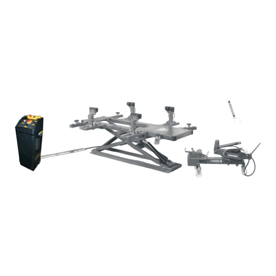
Summary of Contents for BLACKHAWK! PL10C
- Page 1 PL10CMGB REV 12/16 POSTLIFT PL10C / PL20B INSTRUCTION MANUAL (Original manual)
- Page 2 ________________________________________PL10C / PL20B_____________________________________ Index Page Nr. WARNINGS – SAFETY INSTRUCTIONS 3 - 7 INTRODUCTION III) PACKING, TRANSPORT AND STORAGE GENERAL DESCRIPTION TECHNICAL SPECIFICATIONS 10 - 11 INSTALLATION 11 - 13 VII) PULLING SYSTEM 14 - 16 VIII) MAINTENANCE TROUBLESHOOTING ELECTRIC DIAGRAM 19 - 22 HYDRAULIC DIAGRAM XII)
-
Page 3: Warnings - Safety Instructions
________________________________________PL10C / PL20B_____________________________________ I) WARNINGS – SAFETY INSTRUCTIONS The manufacturer hereby refuses to accept any responsibility for injury to persons or damage to equipment or property if it appears that incorrect handling of the lift has occurred. This instructions manual only describes the operating and safety aspects which are necessary to the people who are installing the equipment. -
Page 4: General Precautions
________________________________________PL10C / PL20B_____________________________________ WARNING USE THE LIFT ONLY IF ALL THE SAFETY DEVICES ARE WORKING PROPERLY. IF THESE RULES ARE NOT FOLLOWED, SERIOUS INJURY COULD BE CAUSED TO THE PERSON AS WELL AS IRREPARABLE DAMAGE TO THE LIFT AND THE VEHICLE ON THE LIFT. GENERAL PRECAUTIONS: The operator is bound to follow the regulations which apply in the country in which this lift is installed. -
Page 5: Safety Devices
(Figure 2) Figure 2 RISK OF USE / MAINTENANCE Blackhawk uses material of the highest quality in its lifts. These must be used according to the standard specified, and maintenance must be carried out regularly. RISKS INVOLVED IN POSITIONING A VEHICLE This type of risk may arise if the vehicle is not properly placed on the rubber supports (figure 3), or if the platforms are not properly aligned with respect to the vehicle. -
Page 6: Risk Of Electrocution
________________________________________PL10C / PL20B_____________________________________ RISK FOR THE OPERATOR (Figure 4) This risk arises in cases when the operator is not standing in the correct place by the pump. When the lift with the vehicle is being lowered, the operator MUST NOT stand below the descending system. It is imperative that the operator MUST be standing in the operating zone during the lifting and lowering operations. - Page 7 Do not use the hydro-electric pump in places where there is a risk of combustible vapours. CAUTION Never let any incompetent or insufficiently trained person use this equipment. DECALS: It is your responsibility to keep all warning and safety decals clean and legible at all times. Please contact BLACKHAWK for free replacement decals.
-
Page 8: Packing, Transport And Storage
If you have questions relating to the POSTLIFT system, please contact BLACKHAWK, or its distributor. III) PACKING, TRANSPORT AND STORAGE... -
Page 9: General Description
________________________________________PL10C / PL20B_____________________________________ IV) GENERAL DESCRIPTION The electric hydraulic lift PL20 can be either placed on the floor or in a pit. It has been designed and manufactured for lifting cars and holding them in elevated position. The main parts of the lift are: welded base moving parts lifting parts... -
Page 10: Technical Specifications
________________________________________PL10C / PL20B_____________________________________ V) TECHNICAL SPECIFICATIONS Lifting capacity: 2500 kg Lifting time: 50 seconds Lowering time: 1 mn 40 seconds Total weight (PL20): 550 kg Total weight (PL10): 1370 kg Noise level: 70 dB(A) / 1m Working temperature: -10°C / +40°C Working environment: covered Dimensions :... -
Page 11: Installation
The concrete floor must have a minimum thickness of 150mm and a resistance of C20/25 (Norm EN206-1) INSTALLATION IN A PIT The lift must be installed following the instructions and civil engineering plans supplied by Blackhawk. WARNING No unauthorised person should be present during installation... -
Page 12: Installation Of Hoses
4. Connect the limit switch cables of the lift to the XT6 connector of the pump circuit board. (Figure 15). FILLING THE HYDRAULIC SYSTEM Fill the oil tank with around 10 litres of hydraulic oil, for example BLACKHAWK oil LX22Y or Fina Hydran TS32 or similar oil. (Figure 16) - Page 13 ________________________________________PL10C / PL20B_____________________________________ WARNING THE FOLLOWING ACTIONS SHOULD BE CARRIED OUT BY AUTHORISED PEOPLE ONLY. First check the following points before connecting the device to the mains: The electrical system in the workplace must have the protective and safety devices required by the applicable standards.
-
Page 14: Vehicle Set-Up
5. Tighten the 3 knobs and the caps securely after repair. VII) PULLING SYSTEM (PL10C version) VEHICLE SET-UP Bring the vehicle on the lift and centre it. For help, place white stripes on the floor at a distance of 550 mm from the frame (on the side). - Page 15 ________________________________________PL10C / PL20B_____________________________________ Figure 20 CLAMPS SET UP Set up the 4 arms. Set up the 4 clamp supports. Tighten the bolts of the clamps’ jaws. Lock the clamp supports by the means of the wedges. Lock into place the 4 arms with the plates and the screws. Lift the whole system and remove the wheel stands.
- Page 16 ________________________________________PL10C / PL20B_____________________________________ Figure 23 SET UP OF THE MEASURING SYSTEM P188 OR SHARK: Look at the operating manual supplied with your measuring system for details. PULLS Set up the clamps or the pulling accessories. Set up the safety cable. Place the arms of the Dozer in order to obtain the pulling angle required.
-
Page 17: Maintenance
In accordance with the legislation, check your lift on a periodic basis. (Different depending on the country where the equipment is used) WARNING Do not repair yourself any defect part of the lift or the straightening system. Repair jobs MUST be performed by a BLACKHAWK representative. -
Page 18: Troubleshooting
________________________________________PL10C / PL20B_____________________________________ IX) TROUBLESHOOTING Detection and repair of faults, if any, should only be done subject to the condition that all the relevant SAFETY REGULATIONS as described are followed strictly. ALL RESETTING ACTIONS, REPAIRS TO THE SAFETY DEVICES AND THE ELECTRICAL CONTROLS OF THE LIFT SHOULD BE CARRIED OUT BY AUTHORISED PERSONNEL ONLY. -
Page 19: Electric Diagram
________________________________________PL10C / PL20B_____________________________________ X) ELECTRIC DIAGRAM – 1/2... - Page 20 ________________________________________PL10C / PL20B_____________________________________ ELECTRIC DIAGRAM – 2/2...
-
Page 21: Limit Switch Connection
________________________________________PL10C / PL20B_____________________________________ MAIN SWITCH CONTACTOR NO 4KW 24VCC KA-KA4 RELAIS TRANSFORMER. 230/400/24V 50VA 50/60HZ FUSE HOLDER TRI. 10X38 + FUSE 10AAM FUSE HOLDER 10X38 + FUSE 1A GG FUSE HOLDER 10X38 + FUSE 1A GG LIGHT 24V BUZZER 24V «... - Page 22 ________________________________________PL10C / PL20B_____________________________________ CIRCUIT BOARD CONNECTION...
-
Page 23: Hydraulic Diagram
________________________________________PL10C / PL20B_____________________________________ XI) HYDRAULIC DIAGRAM CYLINDER A CYLINDER B ELECTRO VALVE ASCENT + DESCENT CYLINDER B ELECTRO VALVE ASCENT + DESCENT CYLINDER A ELECTRO VALVE DESCENT FLOW VALVE CHECK VALVE (NON RETURN) MAX PRESSURE VALVE OIL FILTER OIL TANK PUMP 3L MOTOR TRI. -
Page 24: Spare Parts
________________________________________PL10C / PL20B_____________________________________ XII) SPARE PARTS DOZER ITEM REFERENCE DESCRIPTION QUANTITY S064A194 BLACKHAWK DECAL S064A057 DECAL SAFETY CABLE S064A188 BLACKHAWK DECAL S064A296 SERIAL Nr. PLATE S064A218 INDIAN HEAD DECAL... - Page 25 WASHER M20 S110A034 SPRING D=25x130 S950P421 DOZER BASE MBAF3665 SCREW M36x220 MWAE1360 WASHER M36 ARC1610 CYLINDER P790H HYDROPNEUMATIC PUMP (*PL10B version) 29** PMP8110 HYDROPNEUMATIC PUMP (**PL10C version) 30** S950A945 PUMP SUPPORT (**PL10C version) NOTE : * &* * Not shown.
- Page 26 ________________________________________PL10C / PL20B_____________________________________ PL122 ITEM REFERENCE DESCRIPTION QUANTITY S900A760 VERTICAL SUPPORT ASS' Y S950A647 S950A648 BOTTOM LOCK PLATE MABC1643 HEX. BOLT M16x80 MWAE1160 WASHER M16 S111A031 THREADED PLATE (Till S / Nr 1-776) S111A031A THREADED PLATE (From S / Nr 1-777 and up) MBBF823 SCREW M8x25 S950A573...
- Page 27 ________________________________________PL10C / PL20B_____________________________________ S299A018 ITEM REFERENCE DESCRIPTION QUANTITY ACP2018101 CLAMP PLATE ACE5056103A CLAMP ARM MABC1643 BOLT HEX. M16x80 MBCB817 SCREW HSHC M8x12 MWSB1160 WASHER M16 S950A570 CLAMP FLAG WELDMENT ACE4080110X SPRING MNDB1160 NUT HEX. M16 MWAE1160 WASHER M16 MNBE1160 NUT H.T M16 Screw package for 4 clamps : S900A731...
- Page 28 ________________________________________PL10C / PL20B_____________________________________ PL100B : POSTLIFT PARACHUTE VALVE ADJUSTMENT...
- Page 29 MBAF615 SCREW HSHC M6x10 S646A137 HYDRAULIC HOSE 9M S646A138 HYDRAULIC HOSE 6M50 S410A148 CONNECTOR 10 POLES MNDF1100 NUT M10 S064A217 BLACKHAWK DECAL MBEF619 SCREW M6x20 S057A001 SPRING PIN S101A828 HOSE PROTECTIVE PLATE S242A026 ANCHOR BOLT S900A795 PAD ASS’Y – COMPLETE...
- Page 30 ________________________________________PL10C / PL20B_____________________________________ ITEM REFERENCE DESCRIPTION S064L080 DECAL 2500Kg MAX. S101B369 HOSE FIXING PLATE S101B370 LIMIT SWITCH PLATE SUPPORT MQAC1035 RETAINING RING D=35 MHBC621 SCREW M6x20 MBAF419 SCREW HSHC M4x16 S030A058 CYLINDER – WITHOUT PARACHUTE S096A171 BANJO BODY 1/4” S096A146 BANJO FITTING 1/4”...
- Page 31 ________________________________________PL10C / PL20B_____________________________________ PL101B: ELECTRIC PUMP ASSEMBLY...
- Page 32 ________________________________________PL10C / PL20B_____________________________________ ITEM REFERENCE DESCRIPTION QUANTITY S001A091 CUPBOARD S037A127 COMPONENTS SUPPORT S042A088 FRONT COVER S042A089 CONTROL BOARD S372A041 MAIN SWITCH S885A416 FUSE HOLDER 3 x 10x38 S885A417 FUSE HOLDER 2 x 10x38 S410A145 CONTACTOR 4Kw S410A146 TRANSFORMER S198A022 CIRCUIT BOARD S376A005 WARNING LIGHT S980A142...
-
Page 33: Maintenance Booklet
________________________________________PL10C / PL20B_____________________________________ XIII) MAINTENANCE BOOKLET INITIAL TEST Description of the test Notes Check floor consistency □ □ □ Check safety distances (from the walls, columns, ceiling and other machines) □ □ □ Check electricity supply line □ □ □ Check compressed air supply line (depending on the lift model) □... - Page 34 ________________________________________PL10C / PL20B_____________________________________ PERIODICAL OR OCCASIONAL SERVICE Description of the test Notes □ □ □ Check lift maintenance and cleaning Check operation of the mechanical safety systems □ □ □ Check operation of the electrical safety systems □ □ □ Check oil level □...
- Page 35 ________________________________________PL10C / PL20B_____________________________________ PERIODICAL OR OCCASIONAL SERVICE Description of the test Notes □ □ □ Check lift maintenance and cleaning Check operation of the mechanical safety systems □ □ □ Check operation of the electrical safety systems □ □ □ □...
- Page 36 ________________________________________PL10C / PL20B_____________________________________ REPAIR Fault: Action: Date Stamp and signature REPAIR Fault: Action: Date Stamp and signature...
-
Page 37: Declaration Of Conformity
________________________________________PL10C / PL20B_____________________________________ DECLARATION OF CONFORMITY... - Page 38 ________________________________________PL10C / PL20B_____________________________________ BLACKHAWK SAS All rights reserved International Sales BP 5 – 67026 Strasbourg Cedex - F RANCE Tel: +33 3 88 65 76 30 – Fax: +33 3 88 65 76 31 E-Mail : blackhawk-export@snapon.com - www.blackhawk.fr France – Benelux BP 5 –...
Need help?
Do you have a question about the PL10C and is the answer not in the manual?
Questions and answers
Full WIRING FITING video and design wiring for CL10 PROPARLI WIRING