Subscribe to Our Youtube Channel
Summary of Contents for Breezair IWC 10
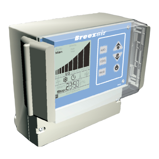
- Page 1 ® I n s t a l l a t i o n & O p e r a t i o n M a n u a l I n d u s t r i a l W a l l C o n t r o l - I W C 1 0 ( i n c o r p o r a t i n g S m a r t H u b a n d F a u l t I n d i c a t i n g f e a t u r e s )
-
Page 2: Kit Components
Safety / Kit Components SAFETY Please read this manual carefully. Your failure to do so could result in injury to you or damage to the cooler and property. Disconnect electrical power at the fuse or circuit breaker box and turn OFF the isolating switch located inside the cooler on the Electronics Module before you begin to install the cooler. - Page 3 Locating the Sensor & Wall Control REMOTE SENSOR LOCATION Mount the remote sensor in a central location within the room or area where you want the temperature to be controlled. When selecting a position for the remote sensor avoid the following locations: Direct sunlight Outside walls Direct heat sources...
-
Page 4: Installing The Wall Control
Installing the Wall Control The Breezair communications cable (4 way plug) and the Breezair sensor cable (6 way plug) will both pass through one gland. See Fig 6 for recommended cable entry utilisation. Connect cables, plugs and glands as indicated in the wiring diagram (Fig 6 &... -
Page 5: Getting Started
Getting Started AT POWER UP SERVICE When power is first applied to the Wall Control there are 3 possible responses depending on what is connected to the Wall Control. When the Wall Control is connected directly to an ICON cooler without any Hubs, either on a single cooler installation or during individual cooler commissioning on a multiple cooler installation, the Wall Control will display SERVICE... - Page 6 Getting Started SETTING THE CLOCK IMPORTANT Please read the application notes before programming this controller. When the Wall Control is first installed, it will show four flashing clock digits. Set the clock on the Wall Control before proceeding with any other programming. Programming can only be done with the Wall Control switched OFF.
- Page 7 Programming Wall Control PROGRAMMING THE WALL CONTROL The Wall Control can only be programmed in the OFF mode. If the control is ON, press the button to enter OFF mode. To enter the PROGRAM mode hold the PROG button down for over 3 seconds. The symbol will start flashing.
- Page 8 Programming Wall Control HUMIDITY CONTROL PROGRAM (continued) To change the Humidity Set Point Hold down the button for over 3 seconds to enter PROGRAM mode. PROG Press the button until the symbol is flashing, then press the button. The AUTO current humidity setting will flash as two digits on the clock (Fig 21).
- Page 9 Programming Wall Control 7-DAY TIMER PROGRAM (continued) Any day that has start and stop times set and the day switched ON will show brackets for the day. Any day that has start and stop times set and the day switched OFF will show no brackets. Any day that has start and stop times set to 00.00 will show no brackets.
-
Page 10: Drain Mode
This section ONLY applies to any new installations commissioned since January 2006, in which IWC05’s (part no. 111087) and Smart-Hubs (part no. 111070) are installed. Installations prior to that date do NOT have any fault indicating features when multiple Breezair coolers are connected to original hubs. - Page 11 ONLY correct RJ max 40m ! connectors and crimping tools HUB 2 CPMD Cables supplied by Breezair are 26AWG, 7/016, 4 MASTER core & 6 core flat ALWAYS route cables at least 300mm away from regular power cables and high power machines.
- Page 12 ILL1331-A Evaporative Cooling Control Manual. Seeley International Pty Ltd, Adelaide, South Australia. ACN 054 687 035. As the policy of the company is one of continuous product improvement, all specifications are subject to change without notice. 828527-J AU 1011...


Need help?
Do you have a question about the IWC 10 and is the answer not in the manual?
Questions and answers