
Related Manuals for WM Systems M2M Easy 2S NB

Summary of Contents for WM Systems M2M Easy 2S NB
- Page 1 M2M Easy 2S NB ® with Impulse firmware Installation Guide ____________________________________ Doc v 1.20 2019-09-06...
- Page 2 Document specifications This documentation was made for the M2M Easy 2S NB with the impulse counter firmware ® WM Systems LLC. version, which were developed by This document contains the step-by-step description of its installation, the program update process and the detailed introduction of the setup parameters necessary for its operation.
-
Page 3: Table Of Contents
Table of Contents Connecting the ports ..................4 1.1 Connectivity.......................... 4 1.2 Cabling and wires ........................5 1.3 LED signals ........................... 8 1.4 Operation requirements ....................... 12 Installation of the device ................13 2.1 Installation on location site ....................13 2.2 Turning on the device ...................... -
Page 4: Connecting The Ports
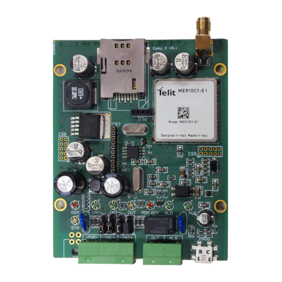
Chapter 1. Connecting the ports 1.1 Connectivity Input, output connections 1 – SIM-card holder (push-insert) 2 – SMA antenna connector (Narrow Band antenna, 50 Ohm) 3 – PWR +/-: Power supply connector (8-24VDC, min. 300mA) 4 – IN1, IN2: 2pcs connector for input lines (for impulse capable meters) 5 –... -
Page 5: Cabling And Wires
1.2 Cabling and wires Preparation Take the 4 spacer fixing tabs provided with the device, and place them into the PCB holes as shown in the picture. Prepare a screwdriver, the 2 terminal blocks provided with the device, and the stripped wire pair necessary for connection, with appropriate distinctive colors (power connector –... - Page 6 Input line operation mode (selection by jumpers): Contact mode (DRY) o Put the jumper (CLOSE) on the IN1 or IN2 line’s 2-pins (two pair of pins), each pair must be jumpered on the closer side of the terminal block (connector) –...
- Page 7 Voltage mode (WET) o Put the jumper on the IN1 or IN2 line’s 2-pins (two pair of pins), each pair must be jumpered closer to the LED side – as you can see in the following picture. Signal levels (WET mode – voltage input): ...
-
Page 8: Led Signals
Connecting the power supply The 8-24V power-supply voltage (typically 12V power adapter, or 24V power supply) can be connected to the PWR input through a wire pair. When connecting the power, the device will be immediately started to operating, when the PWR LED will indicate it with the appropriate color/light. - Page 9 Inactive Signs the presence of the processor power Operation green lights supply (3,3V) GSM: wireless network status LED - The numbers of the GSM LED flashing sequence signs the current RSSI signal strength of the wireless network (more flashes are meaning a better signal reception). There is 10 seconds between the flash signals.
- Page 10 Failure codes – for signing the device opreation troubles – in case of a failure, read the Troubleshooting Chapter. 1 flash - Module failure Easy 2S NB The serial connection is not operating properly between the module and the board.
- Page 11 5 flashing – the GPRS is allowed (GPRSEN=1), but the device cannot login to the GPRS network Possible reasons: o wrong APN settings o the GPRS service is inactive for the SIM card o low signal strength o the RADIUS server is out of operation o maintenance/service tasks by the M.O.
-
Page 12: Operation Requirements
Main important signals of LED flashing/light: not lights: the module was turned off longer periodic flashing: 600 msec filling in / 600 msec filling out: the module not registered to the network (possible causes: no SIM card, PIN authorization failure, network search is in progress, login is in progress, etc.) ... - Page 13 EasyTerm ® Downloading the configurator application from our website, at the Downloads / M2M Easy 2S NB product – Windows ® 7 / 8 / 10 version: http://www.m2mserver.com/m2m-downloads/EasyTerm_v1_3_5_EN.ZIP M2M Easy 2S NB V23 R08 I09 NB ® firmware (system software – uploaded to the device ...
-
Page 14: Installation Of The Device
Chapter 2. Installation of the device EasyTerm Check the current firmware version of the device (SWVER value in the application). If V23 R08 I09 NB the version is not or newer then refresh the firmware to the latest downloadable version! 2.1 Installation on location, site Take care that the device is not under power voltage, it is turned off and the LEDs lights are not lighting or flashing before continue the following steps! - Page 15 When the power voltage added, the devices turns on. The green PWR LED continuously lights. If the input(s) are wired then the IN1, IN2 LEDs are continuously lights with green. Then later the MDM RDY LED blinks a several times with red, that the cellular modem is started.
-
Page 16: Connecting The Device To A Computer
Chapter 3. Connecting the device to a computer 3.1 Required software components The necessary softwares can be downloaded from our website – registration is required. http://m2mserver.com/en/products/m2m-easy2s-nb-impulse/ At the Download part download the following files: EasyTerm configuration application (v1.3.5) File EasyTerm_v1_3_5_EN.ZIP Contains: ... -
Page 17: Introducing The Easyterm Tool
Chapter 4. EasyTerm (configuration, software refresh) 4.1 Introducing the EasyTerm tool The device is shipped with uploaded firmware and pre-defined factory configuration settings. EasyTerm The customization of the configuration is possible by the ® software (via micro USB cable). This tool is suitable for checking and monitoring the current operation of the communicator device or refresh its firmware. -
Page 18: Connecting To The Device
3 – Terminal window 4 – File handling 5 – Parameter configuration 4.2 Connecting to the device a.) USB connection Connection In the settings window (1), at the Serial Port tab choose the proper and available COM port for the Serial port field. You can remotely access the device through celluar network at the TCP-IP tab. - Page 19 enable By the REBOOTDAY parameter you can the industrial- and safety standard daily once device restart event. Push the Connect button for the cellular network connection. (The button is active only if the USB serial / or TCP-IP connection is currently inactive (Close status)).
- Page 20 In case of any failure read the Troubleshooting chapter! Status window (2): connected When the „ ” title appears, this means that the serial connection to the device was performed succesfully. The „ disconnected ” assigns the disconnection of the device from the USB serial port, which means that it is not available through the port (reconnect the cable and the device or restart device when it is necesssary) –...
-
Page 21: Status And Device Data
4.3 Status and device data In the Status window (2) you will receive the device identifiers as IMEI number (cellular modem identifier), Easy 2S ICC (SIM card identifier), HW ID ( unique hardware ID), SW VER (firmware version), IP ADDR. (modem IP address on the network). -
Page 22: File Handling
EasyTerm The Autolog feature is enabled by default, which means that the is generating and writing a log file into the directory where the program was started. You can disable this feature when it is not necessary to use. The messages will be scrolled down – to the last message - automatically. If the scrolling is too fast (e.g. - Page 23 Value When you’ll modify a parameter , the program will be assigning the change by bold highlight. If you click on a parameter name, the hints of the current parameter will be displayed in a small sub- window below the current line - as a help for the better understanding and configuration. (When you click again to the window, the small window will disappear).
-
Page 24: Firmware Upload/Refresh
If you choosed the Select All before you push the Write config then all listed parameters were sent. (The further – not listed - parameter grousp will be not sended.) If you wouldn’t like to send all listed parameter to the device then push to the Deselect all and mark only the required parameters on the parameter groups which you are attempt to sended. - Page 25 Terminal window (3) The installation progress can be followed at the , and by the progress Wait for indicator bar at the Upload part, and due to the status messages. First, the „ bootloader…” Sending file, please wait…” message will appear, then soon you will receive the „ title.
- Page 26 During the installation you can see the „Sending file.. please wait…” message. Wait for the finishing the upload method and the end of the installation! „File transfer successful…” At the end of the installation you will get the message then the device restarts and it will be disconnected! The serial port will be closed. Serial Port For connecting again, Open the connection.
-
Page 27: Device Restart
For the proper centrel installation, the relevant ftp parameters must be defined first. When you were Started the remote installation, and the ftp server is available, in the first phase the firmware download will be started. This will be assigned by the status messages hereby – according to the serial port firmware refresh. - Page 28 The device will execute the ERASECONF command. After 30 seconds, the device will be rebooting when the ^SHUTDOWN meessage appears. The status will be faded out during the config restore method. Important! The device will be started with the standard factory settings, without loading any further customized configuration settings! Therefore, please open the configuration file and send it (Write conf.
- Page 29 Chapter 5. Configuring the device The device is capable for using and operating as an impulse counter and wireless transmitter. Before the first usage and befor configuring the device, download the factory default configuration .CFG file from our website (EASY2S_V23RS08I_NB_EN.cfg). EasyTerm Load into the application (Load File…...
- Page 30 At the value, you have to define the APN name for the SIM-card related GPRS data package service. When using a username or password are needed for the access – e.g. in case of chap authentication – then define the values based on the information proven by your mobile service provider.
-
Page 31: Impulse Counter Settings
Check that the IPPROTO protocol’s format is TCP. When you’ve changed one of the listed parameter values, then the program will highlight the changed value lines by bold. Selected For sending the listed parameter values for the device (regarding the coloumn) –... - Page 32 enables ROAMING feature the roaming operation on the mobile network, which is necessary to be also supported by the mobile operator of the SIM card. When you are attempted to use the roaming, then you have to fill the value country code prefixes (e.g. the Germany +49 prefix for in case of national usage or the 0049 prefix usage in case of...
- Page 33 Note, that after the data sending, the counter will be reseted and the counting will be started again (from 0 by adding the incoming impulse signals).
-
Page 34: Firmware Update/Refresh From Ftp Server
5.5 Firmware update/refresh from FTP server The saved configuration can be distributed for one or multiply devices. The ftp server usage prequisite is for the device to access the ftp server IP address through the mobile network. By the FTPSERVER parameter you can define the ftp server IP address. -
Page 35: Troubleshooting
Chapter 6. Troubleshooting 6.1 A failure signed by the LED flashing 1. The MDM RDY (red) LED is lighting continuously or flashing slowly – the SIM card is not inserted properly. Turn off the device, then remove the SIM card then insert it again. Please, check that you’ve inserted the SIM card properly into the device. - Page 36 Login Failed Terminal window If you’ve received the message in the (3) several times, then repeat these all above. In the next possible failure status cases you can found some examples about the operation malfunction and failure status. The figures will help you to identify about the proper situation. No available signal strenght/no antenna fitted: in case of CSQ 0 value, check that the antenna was mounted and fitted to the device SMA antenna port and wait for 30...
- Page 37 Not NB IoT or not Narrow Band SIM card: When the currently used SIM card is valid but not useful for Narrow Band and NB IoT networks, the GSM STATE will be yellow and the GPRS STATE will be still grey. The modem can see the APN, and was registering to the mobile network, but cannot get IP address from the provider, therefore the connection is not live.The modem will be...
-
Page 38: Support Availability
Chapter 7. Support availability Should you have any questions regarding the usage of the device, you can contact us in the following ways: Email: iotsupport@wmsystems.hu Telephone: +36 20 333 1111 7.1 Support help For identifying the device, please, use the sticker on the PCB, which contains important information to the support staff. -
Page 39: Legal Notice
WM Systems LLC., with clear indication of the source. The pictures in the user guide are only for illustration purposes. WM Systems LLC. does not acknowledge or accept responsibility for any mistakes in the information contained in the user guide.
Need help?
Do you have a question about the M2M Easy 2S NB and is the answer not in the manual?
Questions and answers