Table of Contents
Advertisement
Advertisement
Table of Contents

Related Manuals for Kity PV 6000

Summary of Contents for Kity PV 6000
- Page 1 PV 6000 (Art.Nr. 301 3506 916, 301 5307 916) Holzspalter Originalbetriebsanleitung Hydraulic Log Splitter Translation from the original instruction manual Fendeur hydraulique Traduction du manuel d’origine Hidravlični cepilnik drv Prevod iz originalnih navodil za uporabo...
- Page 2 Slovakia France Len pre štáty EÚ Pour les pays européens uniquement Elektrické náradie nevyhadzujte do komunálneho Ne pas jeter les appareils électriques dans les odpadu! ordures ménagères! Podía európskej smernice 2002/96/EG Conformément à directive européenne nakladani použitými elektrickými 2002/96/EG relative aux déchets d’équipe- elektronickými zariadeniami a zodpovedajúcich ments électriques ou électroniques (DEEE), et ustanovení...
- Page 3 PV 6000 Holzspalter 4–33 Hydraulic Log Splitter Fendeur hydraulique 34–63 Hidravlični cepilnik drv...
- Page 4 Günzburger Straße 69 D-89335 Ichenhausen Verehrter Kunde, Wir wünschen Ihnen viel Freude und Erfolg beim Arbeiten mit Ihrer neuen Kity Maschine. Hinweis: Der Hersteller dieses Gerätes haftet nach dem geltenden Produkthaftungsgesetz nicht für Schäden, die an diesem Gerät oder durch dieses Gerät entstehen bei: •...
- Page 5 Manufacturer: Woodster GmbH Günzburger Straße 69 D-89335 Ichenhausen (Germany) Dear Customer, We hope you have a pleasant and successful working ex- perience with your new Woodster machine. Please note: According to the applicable product liability law, the manufacturer of this device is not liable for damage that arises due to or in connection with this device in the event of: •...
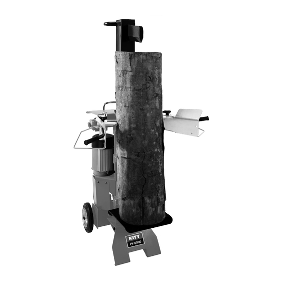
- Page 6 Griffschutz Halterung für Tisch (vorn) Halterung für Tisch (seitlich) Tischverriegelung Spalttisch Entlüftungskappe/Öleinfüllschraube Grundgestell Räder Schalter und Stecker Hubeinstellstange Motor Schutzbügel PV 6000 Lieferumfang Hydraulischer Holzspalter Kleinteile/Beipackbeutel Betriebsanleitung Technische Daten Maße T/B/H 700/450/1550 Tischhöhe mm 280/570/770 Arbeitshöhe mm Holzlänge cm 58/77/106...
- Page 7 Table locking levers Cleaver table Vent cap/Oil filler plug Base frame Wheels Switches and plugs Stroke adjustment rod Motor Hoop guards PV 6000 Scope of delivery Hydraulic Log Splitter Small parts/Accessory bag Operating instructions Technical data 700/450/1550 Dimensions L/W/H 280/570/770...
- Page 8 Warnsymbole/Hinweise Vor Inbetriebnahme das Handbuch lesen Unfallsichere Schuhe benutzen Arbeitshandschuhe verwenden Gehörschutz und Schutzbrille benutzen Schutzhelm benutzen Zutritt verboten für Unbefugte Rauchverbot im Arbeitsbereich Kein Hydrauliköl auf den Boden laufen lassen Halten Sie Ihren Arbeitsbereich in Ordnung! Unordnung kann Unfälle zur Folge haben! Wenn ein Kran verwendet wird, legen Sie den Heberiemen um das Gehäuse.
- Page 9 Warning symbols/Notes Please read the manual before start-up Wear safety footwear Wear work gloves Use hearing protection and safety goggles Wear a hardhat Authorised personnel only No smoking in the working area Do not spill hydraulic oil on the floor Keep your workspace clean! Untidiness can cause accidents! If a crane is used, put the lifting belt round...
-
Page 10: Allgemeine Sicherheitshinweise
Gerät nicht liegend transportieren! Spaltgut auf den Spalter stellen. Hebelarme immer zum Spaltgut drücken. Sobald Spaltvorgang einsetzt und Spaltmesser in das Holz eindringt, Hebelarme bei gedrücktem Zustand nach außen zurück führen, sodass Spaltgut frei ist. Vor Inbetriebnahme der Maschine mit der Zweihand hebel- Bedienung vertraut machen! Die Gebrauchsanweisung aufmerksam lesen. -
Page 11: General Safety Instructions
Place the material to be split on the splitter. Always press the lever arms in the direction of the material to be split. Once it begins to split and the cleaver blade penetrates into the wood, guide the lever arms back to the outside, while they are still pressed down, so that the material to be split is free. -
Page 12: Bestimmungsgemäße Verwendung
Zusätzliche Sicherheitshinweise für Holzspalter • Der Holzspalter darf nur von einer einzelnen Person be dient werden. • Tragen Sie Schutzausrüstung (Schutzbrille/-visier, Hand schuhe, Sicherheitsschuhe), um sich vor mögli- chen Ver letzungen zu schützen. • Niemals Stämme spalten, die Nägel, Draht oder andere Gegen stände enthalten. -
Page 13: Proper Use
Additional safety instructions for the log splitter • The log splitter must only be operated by a single per- son. • Wear protective equipment (safety goggles/protective visor, work gloves, safety shoes) to protect yourself from possible injuries. • Never, cleave logs containing nails, wire or other ob- jects. -
Page 14: Montage
nicht offensichtliche Restrisiken bestehen. • Restrisiken können minimiert werden, wenn die Sicher- heitshinweise und die Bestimmungsgemäße Verwen- dung, sowie die Bedienungsanweisung insgesamt be- ach tet werden. Transport Transport von Hand, Fig. 3 Fig. 3 Um den Holzspalter zu transportieren, muss man das Spaltmesser A ganz nach unten fahren. -
Page 15: Transport Instructions
• Furthermore, unapparent risks may remain, despite of all the measures taken. • Residual risks can be minimized, if the safety instruc- tions, the proper use and the operating instructions are observed. Transport instructions Transport by hand, Fig. 3 To transport the log splitter, completely retract the cleav- er blade A. - Page 16 Bedienarme montieren, Fig. 4.2 Fig. 4.2 • Bedienarm (A) in die Schaltwippe (C) einführen, Sechskantschraube (D), Scheibe Sicherungsmutter verschrauben. Die Sicherungsmutter nur so festziehen, dass sich der Bedienarm noch bewegen lässt. • Nun den Bedienarm (B) nach der beschriebenen Methode rechts befestigen. •...
-
Page 17: Working With The Log Splitter
Mounting the control arms, Fig. 4.2 • Insert the control arm (A) in the rocker switch (C), and screw it in place with the hexagon bolt (D), the washer (E) and the safety nut. Tighten the lock nut so the con- trol arm can still be moved. - Page 18 Tischhöhe einstellen, Fig. 5 Fig. 5 Oberere Position des Tisches für Stämme bis 58 cm, mittlere Position des Tisches für Stämme bis 77 cm, untere Position des Tisches für Stämme bis 106 cm Funktionsprüfung Vor jedem Einsatz soll eine Funktionsprüfung gemacht werden.
- Page 19 Adjusting the table height, Fig. 5 Upper tabletop position, for logs up to 58 cm Middle tabletop position, for logs up to 77 cm Lower tabletop position, for logs up to 106 cm Functional test A functional test must be performed prior to each use. Action: Result: Press both handles down.
-
Page 20: Elektrischer Anschluss
Ein-/Ausschalten, Fig. 8.1 / 8.2 Fig. 8.1 Öffnen Sie die Schutzkappe (C). Drücken Sie den grünen Knopf (A) zum Einschalten. Drücken Sie den roten Knopf (B) zum Ausschalten. Drücken Sie den Not-Aus-Knopf (D) bei Gefahr. Hinweis: Überprüfen Sie vor jedem Gebrauch die Funkti- on der Ein-Ausschalt-Einheit durch einmaliges Ein- und Ausschalten. -
Page 21: Electrical Connection
Switching on / off, Fig. 8.1 / 8.2 Open the protective cap (C). Press the green button (A) to switch the appliance on. Press the red button (B) to switch the appliance off. Press the emergency stop (D) in the event of emergen- cies. -
Page 22: Wartung Und Reparatur
Drehstrommotor 400 V/ 50 Hz Netzspannung 400 Volt / 50 Hz. Netzanschluss und Verlängerungsleitung müssen 5-adrig sein = 3 P + N + SL. - (3/N/PE). Verlängerungsleitungen müssen einen Mindestquerschnitt von 1,5 mm² aufweisen. Der Netzanschluss wird mit maximal 16 A abgesichert 400 V/ 50 Hz MOTOR SWITCH(KOA7) -
Page 23: Maintenance And Repair
Three-phase motor 400 V/ 50 Hz Supply voltage 400 V/ 50 Hz The mains connection and the extension cable must be 5-wire = 3 P + N + SL. - (3/N/PE). The extension cables must have a minimum cross section of 1.5 mm². - Page 24 tank, Ölpumpe und Steuerventil. Überprüfen Sie den Öl- stand regelmäßig vor jeder Inbetriebnahme. Zu niedriger Ölstand kann die Ölpumpe beschädigen. Der Ölstand muss innerhalb der Markierung am Ölmessstab sein. Die Spaltsäule muss vor der Prüfung eingefahren sein, die Maschine muss eben stehen. Wann wechsle ich das Öl? Erster Ölwechsel nach 50 Betriebsstunden, danach alle 500 Betriebsstunden.
- Page 25 oil pump and control valve. Check the oil level regularly, before each use. Too low an oil level can damage the oil pump. The oil level must lie within the marks on the dip- stick. The cleaver column must be retracted before checking the oil;...
- Page 26 tralem Reinigungsmittel angefeuchteten Tuch reinigen, keine Lösungsmittel wie Alkohol oder Benzin verwenden, weil sie die Oberflächen angreifen können. Öle und Schmierfette außerhalb der Reichweite von un- befugtem Personal halten; die Anweisungen auf den Behältern aufmerksam durchlesen und genau befolgen; direkten Kontakt mit der Haut vermeiden und nach Be- nutzung gut abspülen.
- Page 27 Keep oils and lubricants out of the reach of unauthorized personnel; read the instructions on the containers care- fully and follow them without fail; avoid direct contact with skin and rinse well after use. m Accident prevention standards The machine must only be operated by qualified person- nel, who are familiar with the contents of this manual.
- Page 28 unter Druck stehenden Leitungen explodieren: man muss daher darauf achten, dass man nicht mit den auslau- fenden Flüssigkeiten in Berührung kommt. Abbau und Entsorgung Die Maschine enthält keine gesundheits- oder umwelt- schädlichen Stoffe, da sie aus völlig wiederverwertbaren oder auf normalem Wege zu entsorgenden Materialien ge- baut wurde.
- Page 29 Dismounting and disposal The machine does not contain any harmful or polluting substances, as it is made of completely recyclable mate- rials or of materials that can be disposed of in the normal way. For disposal, contact specialist companies or qualified personnel who are well acquainted with the potential dangers and who have read and follow the present operat- ing instructions strictly.
-
Page 30: Eg-Konformitätserklärung
Richtlinien entspricht. Bei einer Änderung an der Maschine verliert diese Erklärung ihre Gültigkeit. Bezeichnung der Maschine: Hydraulik-Holzspalter Maschinentyp: PV 6000 Artikelnummer: 301 5306 916 / 301 5307 916 Einschlägige EG-Richtlinien EG-Maschinenrichtlinie 98/37/EG (bis 28.12.2009), EG-Maschinenrichtlinie 2006/42/EG (ab 29.12.2009), EG-Niederspannungsrichtlinie 2006/95/EWG, EG-EMV Richtlinie 2004/108/EWG. -
Page 31: Eg-Declaration Of Conformity
In case of modifications to the machine, the present declaration loses its validity. Designation of the machine: Hydraulic Log Splitter Model: PV 6000 Item number: 390 5306 916 / 301 5307 916 Relevant EC directives: EC machine directive 98/37/EG (< 28.12.2009), EC machine directive 2006/42/EG (>... -
Page 32: Fehlerbehebungsplan
m Fehlerbehebungsplan Bei Störungen, die hier nicht genannt werden, wenden Sie sich an den Kundendienst der Firma scheppach. Störung Mögliche Ursachen Lösung Gefahrenstufe Die hydraulische Pumpe Spannung fehlt Prüfen, ob die Leitungen Gefahr eines Stromschlags springt nicht an Stromversorgung haben Dieser Arbeitsgang muss von einem Wartungselektriker... - Page 33 m Troubleshooting plan For faults that are not listed below, please contact the customer service of Scheppach. Problem Possible cause Remedy Hazard classification The hydraulic pump will not No voltage Check whether the lines are Risk of electric shock start supplied with current This operation must be carried out by a...
- Page 34 Fabricant: Woodster GmbH Günzburger Straße 69 D-89335 Ichenhausen Cher client, Nous vous souhaitons une utilisation agréable et réussie de votre nouvelle machine Woodster. Remarque: Conformément à la loi relative à la sécurité des produits en vigueur, le fabricant de cette machine n’est pas res- ponsable des dégâts qui peuvent survenir ou être liés à...
- Page 35 Proizvajalec: Woodster GmbH Günzburger Straße 69 D-89335 Ichenhausen (Nemčija) Spoštovani kupec, Upamo, da bo vaše delo z novo napravo Woodster prije- tno in uspešno. Prosimo preberite: V skladu z obveznim veljavnim zakonom o proizvodu, proizvajalec ne prevzema nobene odgovornosti za pov- zročeno škodo nastalo zaradi ali v povezavi s to napravo kot rezultat: •...
- Page 36 Table de fendoir Capuchon de purge/vis de remplissage d’huile Montant Roues Interrupteur et fiche Tige de réglage du levage Moteur Étrier de protection PV 6000 étendue de la fourniture Fendeuse hydraulique Petit matériel/pochette Manuel d’exploitation Caractéristiques techniques Fig. 2 700/450/1550...
- Page 37 Namizne ročice za zaklepanje Namizni sekač Glava ventila/Čep oljnega filtra Osnovni okvir Kolesa Stikala in vtikači Ročica za uravnavanje giba Motor Varovalni obroč PV 6000 Področje dostave Hidravlični cepilnik drv Majhni deli/Vrečka za dodatke Navodila za delovanje Tehnični podatki 700/450/1550 Dimenzije D/Š/V 280/570/770 Tabela višine mm...
- Page 38 Symboles d’avertissement/avertissements Avant la mise en service, lire le manuel Porter des chaussures de protection contre les accidents Porter des gants de travail Porter une protection auditive et des lunettes de protection Porter un casque de protection Accès interdit aux personnes non autorisées Interdiction de fumer dans la zone de travail Ne pas répandre de l’huile hydraulique sur le sol...
- Page 39 Opozorilni simboli/Navodila Pred uporabo preberite priročnik Uporabljajte zaščitne čevlje Uporabljajte delovne rokavice Uporabljajte zaščito za sluh in zaščitna očala Uporabljajte zaščitno čelado Dostop nepooblaščenim osebam prepove- Kajenje na delovnem območju prepovedano Hidravlično olje ne sme iztekati na tla Ohranite urejeno delovno področje! Neure- jenost lahko povzroči nesrečo! Pri uporabi žerjava, namestite dvižne jerme- ne okoli ohišja.
-
Page 40: Consignes Générales De Sécurité
Poser le bois à fendre sur la fendeuse. Toujours appuyer les bras de levier sur le bois à fendre. Dès que le fendage commence et que le fendoir pénètre dans le bois, rouvrir les bras de levier de manière à libérer le bois à fendre. Avant la mise en service de la machine, se familiariser avec la commande à... -
Page 41: Osnovna Varnostna Navodila
Material za cepljenje položite na cepilnik. Polnilni vzvod ve- dno pritisnite v smer cepljenja materiala. Ko je cepljenje v teku in je sekač zarit v les, vodite polnilni vzvod nazaj na zunanjo stran,medtem ga še vedno potiskajte navzdol, tako, da je material za ceplje- nje prost. -
Page 42: Utilisation Conforme
Consignes de sécurité complémentaires pour fendeuses • La fendeuse ne doit être utilisée que par une seule personne à la fois. • Porter l’équipement de protection (lunettes de protec- tion/écran, gants, chaussures de protection) comme protection contre de potentielles blessures. •... -
Page 43: Preostala Tveganja
Dodatna varnostna navodila za cepilnik drv • S cepilnikom drv lahko upravlja le ena oseba. • Nosite zaščitno opremo (zaščitna očala/zaščitni vezir, delovne rokavice, zaščitne čevlje), da se zaščitite pred nepotrebnimi nezgodami. • Nikoli ne cepite drv v katerih so žeblji, žice ali drugi tujki. - Page 44 • Par ailleurs il est possible qu’il y ait des risques rési- duels non évidents en dépit de toutes les précautions prises. • Les risques résiduels peuvent être réduits à un mi- nimum par l’observation de toutes les consignes de sécurité, une utilisation conforme de l’appareil ainsi que le respect des consignes d’utilisation.
- Page 45 • Poleg tega ostajajo nepričakovana tveganja, kljub upoštevanju vseh varnostnih normativov. • Preostala tveganja lahko minimiziramo ob upoštevanju navodil za varnost, uporabo, ter navodil za delova- nje. Navodila za prevoz Ročen prevoz, Sl. 3 Za prevoz sekača za drva, popolnoma izvlecite rezilo sekača A.
-
Page 46: Consignes De Travail
Monter les bras de commande, Fig. 4.2 Fig. 4.2 • Introduire le bras de commande (A) dans la bascule (C) et serrer avec la vis à six pans (D), une rondelle (E) et l’écrou de sécurité. Serrer l’écrou de sécurité juste assez pour que le bras de commande puisse encore être déplacé. - Page 47 Montaža kontrolne ročice, Sl. 4.2 • Vstavite kontrolno ročico (A) v klecno stikalo (C) ter jo privijte s šest-kotnim vijakom (D), podložko (E) in varnostno matico. Pričvrstite varnostno matico toliko, da se kontrolna ročica da premikati. • Zdaj pritrdite kontrolno ročico (B) na desno, s ponovi- tvijo opisanega postopka zgoraj.
-
Page 48: Mise En Service
Régler la hauteur de la table, Fig. 5 Fig. 5 Position supérieure de la table pour des troncs jusqu’à 58 cm, Position intermédiaire de la table pour des troncs jusqu’à 77 cm, Position inférieure de la table pour des troncs jusqu’à 106 cm Essai de fonctionnement Il convient d’effectuer un essai de fonctionnement avant chaque utilisation. - Page 49 Prilagoditev višine mize, Sl. 5 Pozicija mize zgoraj za drva do 58 cm Pozicija mize na sredini za drva do 77 cm Pozicija mize spodaj za drva do 106 cm Preizkus funkcij Preizkus funkcij se mora izvajati pred vsako uporabo. Dejanje: Rezultat: Sprostite obe ročici navzdol.
-
Page 50: Raccordement Électrique
Mise en marche/à l’arrêt, Fig. 8.1 / 8.2 Fig. 8.1 Ouvrir le cache (C). Pour la mise en marche, appuyer sur le bouton vert (A). Pour la mise à l’arrêt, appuyer sur le bouton rouge (B). En cas de danger, appuyer sur le bouton d’arrêt d’urgence (D). -
Page 51: Električna Povezava
Priklapljanje on/off, Sl. 8.1 / 8.2 Odprite zaščitno kapo (C). Pritisnite zeleni gumb (A), da napravo vklopite. Pritisnite rdeč gumb (B), da napravo izklopite. Pritisnite zaustavitev v sili (D) v primeru sile. Opomba: Pred vsako uporabo preverite delovanje stikal on/off, s vklopom in izklopom naprave. V primeru napake v električnem omrežju, ponovite zagon zaščite (Prednapetostno stikalo) V primeru napake na električnem omrežju, nezgodni... -
Page 52: Maintenance Et Réparation
• Points d’appui quand les câbles d’alimentation sont passés par des fenêtres ou ouvertures de porte. • Points de pliage en raison d’une fixation ou pose inap- propriée des câbles d’alimentation. • Point de coupure dû au passage d’objets sur les câbles d’alimentation. -
Page 53: Vzdrževanje In Popravila
• Stiskanje, ko vode speljujemo skozi okna, vrata ali reže. • Vozli, kot posledica nepravilnega nameščanja ali spe- ljevanja povezovalnih vodov. • Zareze, zaradi križanja povezovalnih vodov. • Poškodbe izolacije, zaradi vlečenja voda iz stenske vtičnice. • Razpoke, kot posledica staranja izolacijskega mate- riala. - Page 54 • Dispositif de protection à deux mains Le système de maintien et de commande doit rester facile à manier. À l’occasion, lubrifier avec quelques gouttes d’huile. • Pièces mobiles - maintenir les guidages du fendoir propres. (salissu- res, copeaux de bois, écorce, etc.) - lubrifier les rails de glisse avec de l’huile à...
- Page 55 delovati brezhibno. Občasno naoljite z nekaj kapljica- mi olja. • Premični deli - Ohranite rezilo sekača čisto (umazanija, ostružki, lu- bje ipd...) - Naoljite drsne tirnice z oljnim sprejem ali z oljno ma- stjo. • Preverjanje nivoja hidravličnega olja. Preverite hidravlične stike in spoje za obrabo in spu- ščanje.
- Page 56 Système hydraulique L’installation hydraulique est un système fermé avec réservoir d’huile, pompe à huile et distributeur de com- mande. Le système monté en usine ne doit pas être modifié ni manipulé. Contrôler le niveau d’huile régulièrement. Un niveau d’huile trop bas peut endommager la pompe à...
- Page 57 Ne spreminjajte in ne prilagajajte s tovarniško prednasta- vljenim sistemom. Redno preverjajte nivo olja. Prenizek nivo olja bo poškodoval oljno črpalko. Redno preverjajte hidravlične in privite spoje za spušča- nje privijte jih če je potrebno. Pred vsakršno kontrolo in popravilom stroja, očistite de- lovni prostor in hranite orodje v dobrem stanju.
- Page 58 lu auparavant le présent manuel. Le programme de maintenance spécifié ici doit être res- pecté aussi bien pour des raisons de sécurité que pour le fonctionnement efficace de la machine. Les étiquettes de sécurité doivent toujours être propres et lisibles et être observées avec précision afin d’éviter des accidents ;...
- Page 59 Zaradi varnostnih razlogov in razlogov brezhibnega de- lovanja stroja, bodite pazljivi na redna vzdrževalna dela, opisana v tem priročniku. Ohranjajte stanje varnostnih opozoril čisto in berljivo. Da boste uspešni pri zagotavljanju varnostni, jim namenite dovolj pozornosti, če so varnostne označbe poškodova- ne, izgubljene ali so bile na delih, ki ste jih morali za- menjati, jih nadomestite z novimi originalnimi označbami, pritrjenimi na predvidene pozicije.
- Page 60 Toute modification apportée à la machine entraîne la nullité de cette déclaration. Désignation de la machine: Fendeuse hydraulique Type de machine: PV 6000 Numéro d’article: 301 5306 916 / 301 5307 916 Les directives CE qui s’appliquent: Directive CE sur les machines 98/37/EG (< 28.12.2009), Directive CE sur les machines 2006/42/EG (>...
-
Page 61: Eg-Izjava O Skladnosti
EC direktiv naštetih spodaj. V primeru predelave naprave, izjava o skladnosti izgubi veljavnost. Imenovanje naprave: Hidravlični cepilnik drv Model: PV 6000 številka proizvoda: 301 5306 916 / 301 5307 916 Veljavne EC direktive: Smernica EC za stroje 98/37/EG (< 28.12.2009), Smernica EC za stroje 2006/42/EG (>... - Page 62 m Programme de dépannage En cas de défaillances non citées ici, veuillez vous adresser au service après-vente de la société scheppach. Défaillance Causes possibles Solution Degré de danger La pompe hydraulique ne Absence de tension Vérifier si les câbles sont Risque de choc électrique démarre pas raccordés à...
- Page 63 m Načrt odpravljanja težav Za napake, ki niso naštete spodaj, se obrnite na službo za stranke v Scheppach-u. Težava Možni vzroki Odprava težav Razvrstitev nevarnosti Hidravlična črpalka ne Ni električne napetosti Preverite, če so vodi Tveganje električnega udara. deluje povezani z električnim To delo naj izvaja električar.
- Page 68 Garantie Garanti Offensichtliche Mängel sind innerhalb von 8 Tagen nach Erhalt der Ware anzuzei- Med denna maskin följer en 24 månaders garanti. Garantin täcker endast material- gen, andernfalls verliert der Käufer sämtliche Ansprüche wegen solcher Mängel. Wir och konstruktionsfel. Defekta delar ersätts utan omkostningar, men kunden står för leisten Garantie für unsere Maschinen bei richtiger Behandlung auf die Dauer der installationen.
Need help?
Do you have a question about the PV 6000 and is the answer not in the manual?
Questions and answers