Advertisement
Quick Links
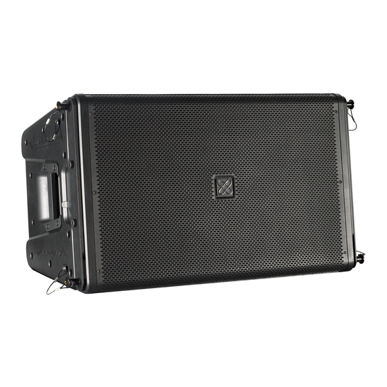
Crest Audio® Versarray™ Mk III FlyQWIK™
Adjustable Rigging System
Crest Audio® Versarray™ VR218 Mk III Ground Stack Kit
Specifications and Instructions
CAUTION ! Before attempting to stack any Versarray™ 112 Mk III / Pro cabinets onto a Versarray™ 218
Mk III / Pro Sub, refer to a qualified professional. The Versarray™ 218 Mk III / Pro Sub and/or speaker
array can fall over from improper suspension, resulting in serious injury and property damage. Use only
the correct mating hardware. All associated rigging is the responsibility of others.
Description
The Crest Audio® Versarray™ VR218 Mk III Ground Stack Kit is designed to allow up to three of the
Versarray™ 112 Mk III / Pro cabinets to be stacked above a Versarray™ 218 Mk III / Pro Sub for ground
stack use. Brackets that bolt to the top of the Versarray™ 218 Mk III / Pro Sub, to interface with the
cabinet rigging hardware are provided, as well as Strapping Plates to provide for strapping the Sub
cabinet down and securing it to the stage or the ground are supplied.
This Kit is an optional piece of the overall rigging system, and it will not be needed if there is no need to
stack VR™ 112 Mk III / Pro cabinets on top of the VR™ 218 Mk III / Pro Sub.
Specifications:
Contents: Two Strap Stacking Brackets (L & R), one Rear Pivot Bar Bracket, two Strapping
Plates (L & R). All required bolts are supplied on the VR™ 218 Sub, and the locking push pins
needed are included on the VR™ 112 Mk III / Pro cabinets.
Height added to Versarray™ 218 Mk III / Pro Sub: 4.93" (12.52 cm)
Material: 5 mm (approx. 7 Gauge) thick solid steel alloy.
Finish: All brackets and plates have a flat black powder coated paint finish.
Maximum Combined Total Stack Angle: Must be less than 30 degrees.
Maximum Number of Cabinets per Sub: No more than 3 maximum
Versarray™ 112 Mk III/ Pro two-way speaker cabinets can only be stacked on top of a Versarray™ 218 Mk
III / Pro Sub when the Sub is located on a substantially level surface, and secured to the stage or ground
with safety straps.
CAUTION ! The Crest Audio® Versarray™ Mk III Ground Stack Kit is designed to be used ONLY in
con- junction with the Versarray™ 218 Mk III / Pro Sub and the Versarray™ 112 Mk III / Pro two-way
speaker cabinets! It is not designed to be used with any other brands of Subs or stacking cabinets!
1
Advertisement

Related Manuals for Crest Audio Versarray Mk III FlyQWIK


Summary of Contents for Crest Audio Versarray Mk III FlyQWIK
- Page 1 Description The Crest Audio® Versarray™ VR218 Mk III Ground Stack Kit is designed to allow up to three of the Versarray™ 112 Mk III / Pro cabinets to be stacked above a Versarray™ 218 Mk III / Pro Sub for ground stack use.
- Page 2 You should not be able to pull these pins out unless the center push-button is fully depressed. The Crest Audio® Versarray™ loudspeaker models should be stacked on top of the Sub only in accordance with the procedures and limitations specified in the User’s Manual and possible manual update notices.
- Page 3 Crest Audio® Versarray™ VR Ground Stack Kit Installation Procedure Installation of each individual bracket and/or plate is started by the removal of the bolts on the top and sides of the cabinet that correspond with the particular bracket being installed. There are 8 bolts on the top of the cabinet and 2 on each side to be removed.
- Page 4 Place the bolts through the mounting holes in the bracket into the holes in the cabinet. See Fig. 6 Figure 6 Slowly tighten down the bolts, while moving the wrench from bolt to bolt. This allows the bolts to tighten the bracket down evenly. This also allows the head of the bolts to grab in the mounting holes and allow for self centering.
- Page 5 Rear Pivot Bar Bracket After the four bolts have been removed, place the bracket into position. Orient it so that the angle part of the bracket is pointing toward the rear of the cabinet. See Fig. 9 Figure 9 Place the bolts through the mounting holes in the bracket into the holes in the cabinet. See Fig 10 Figure 10 Slowly tighten down the bolts, while moving the wrench from bolt to bolt.
- Page 6 Right and Left Strapping Plates Use the following steps to install both the right and left Strapping Plates. After the two bolts have been removed, place the bracket into position. Orient it so that the ear is on the edge of the cabinet. See Fig. 11 Figure 11 Place the bolts through the mounting holes in the plate into the holes in the cabinet.
- Page 7 VR112 MKIII / PRO Cabinets to Ground Stack Brackets Installation Procedure Before attempting to install the VR112 cabinet onto the ground stack brackets, remove the bottom front quick release lock pin. Do this on both sides. See Fig. 13 and 13a. Figure 13 Figure 13a Remove the Pivot Bar hole pin from the Angle Slider Bracket.
- Page 8 Predetermine what angle the first VR112 cabinet will be used in, 0 or 2.5 degrees. Remove the pin from the Lock Pin hole on the Angle Slider Bracket. Adjust the Angle Slider Bracket until the angle ar- row lines up with the desired angle point as shown by the arrow labeled Angle on the Angle Slider Rail. The Ground Stack Kit will only allow for the first cabinet to be adjusted to the angles of 0 degrees and 2.5 degrees.
- Page 9 Figure 17 Using the handle mounted on the back of the cabinet, adjust the back of the cabinet up or down to align the Pivot Bar hole on the Angle Slider Bracket to the pin hole on the Rear Pivot Bar Bracket mounted on the sub.
- Page 10 Installation Procedure for additional VR112 MKIII/Pro Cabinets Start by preparing the first cabinet to receive the second cabinet. This is done by removing the top front quick release lock pins. Slide the front hang straps up and pin them in place using the pins that were just removed.
- Page 11 Remove the Pivot Bar hole pin from the Angle Slider Bracket on the second cabinet. Swing the Pivot Bar up and out of the way. See Fig. 24 and 24a Figure 24 Figure 24a Predetermine what angle the second VR112 will be used in, 0 thru 15 degrees. Remove the pin from the Lock Pin hole on the Angle Slider Bracket.
- Page 12 With help from a second person, lift the VR112 MKIII Cabinet and place it on top of the first VR112 cabinet, engaging the front hang straps of the first cabinet with the strap slots of the second cabinet. See fig. Figure 26 Maneuver the cabinet by hand allowing the Locking Pin to be inserted easily into the holes mating the front hang straps with the strap slots.
- Page 13 Using the handle mounted on the back of the cabinet, adjust the back of the cabinet up or down to align the Pivot Bar hole on the Angle Slider Bracket of the second cabinet to the pin hole on the Pivot Bar of the first cabinet.
- Page 16 QR tag below Features and specifications subject to change without notice. Crest Audio 5022 HWY 493 N. Meridian, MS 39305 (601) 483-5365 FAX (601) 486-1278 Logo referenced in Directive 2002/96/EC Annex IV (OJ(L)37/38,13.02.03 and defined in EN 50419: 2005...
Need help?
Do you have a question about the Versarray Mk III FlyQWIK and is the answer not in the manual?
Questions and answers