Advertisement
Quick Links
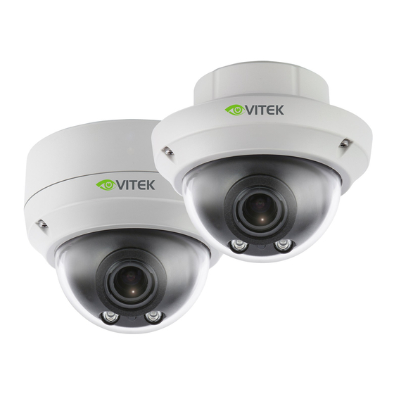
V T D - VD4 MZ 39
FEATURES:
• 1/2.9" 6.64 MegaPixel Sony STARVIS® CMOS Sensor
• 4 MegaPixel Coax Based Camera (2560x1440px @ 30/25fps)
• Outstanding Low Light Performance with Sony STARVIS® Sensor
• 1500' HD-Analog Transmission Distance over Coax (Depending on Cable Characteristics
and Integrity)
• Premium 4MP Multi-format Video Output, Digital: EX-SDI 1.0/ 2.0/ 2.1 (4MP/2MP/1.3MP),
HD-SDI (2MP/1.3MP) HD-Analog: TVI Mode (4MP/2MP/1.3MP) , AHD Mode (4MP/2MP),
CVBS
• F= 3.2~9mm Motorized Zoom Lens with Auto Focus
• Automatically Removable IR Cut Filter by Dual Filter Switch
• True WDR (Wide Dynamic Range) @30/25fps
• 120dB Dynamic Range with DOL(Digital OverLap) WDR @30/25fps
• ROI (Region of Interest) WDR @30/25fps
• Improved Noise Reduction with XD-NR
• DIS (Digital Image Stabilization) Function
• POI Zoom (Point Of Interest), Smart Motion Zoom, Preset Zoom, Home Position
• Privacy Mask, Defog, Sens-up(~x32), D-WDR, BLC/HLC, Mirror/Flip, Flickerless, Brightness,
Smart IR, Lens Initialize, Title Set, Color D/N
• High performance at Low Light Sensitivity (Sens-up On)
• Variety of Resolution : 1440p/1080p/720p Without Loss of FOV (Field of View)
• OSD Menu for Easy Installation and Maintenance
• Circuit Protection Protects Against Faulty Connection in Power Polarity
• Isolated Power Supply Protects Against Ground Loop Problem
• COC Control through HD-TVI (Pelco-C®) or AHD
• IP68 (VTD-VD4MZ39, VTC-IR4MZ39), IK10 (VTD-VD4MZ39)
• 12VDC, 24VAC Operation
VIRTUOSO HI DEFINITION
OVER COAX CAMERAS
Premium 4 Megapixel Indoor/Outdoor
6-in-1 HD/EX-SDI / TVI / AHD / CVI /
CVBS Motorized Varifocal Cameras
V TC - CB 4M Z 3 9
V TC- IR 4 M Z 39
COAX
Advertisement

Related Manuals for Vitek VIRTUOSO VTD-VD4MZ39

Summary of Contents for Vitek VIRTUOSO VTD-VD4MZ39
- Page 1 VIRTUOSO HI DEFINITION OVER COAX CAMERAS Premium 4 Megapixel Indoor/Outdoor 6-in-1 HD/EX-SDI / TVI / AHD / CVI / CVBS Motorized Varifocal Cameras V T D - VD4 MZ 39 V TC - CB 4M Z 3 9 V TC- IR 4 M Z 39 FEATURES: •...
-
Page 2: Table Of Contents
Table of Contents Safety Precautions..........Overview: VTC-CB4MX39....... Overview: VTD-VD4MZ39....... 8-15 Overview: VTC-IR4MZ39......... 16-20 Connections: VTD-VD4MZ39, VTC-IRMZ39... 21 OPERATING INSTRUCTIONS....22-38 OSD Menu.......... 22-24 Zoom / Focus........24-26 Exposure..........27-28 WDR............ 29-30 XD-DNR..........Day / Night.......... 31-33 Picture Adjustment......33-35 Special Functions......35-37 System.......... -
Page 3: Safety Precautions
Safety Precautions To prevent fire or shock hazard, do not expose the unit to rain or moisture. To prevent electric shocks and risk of fire hazards, do NOT use other than with a specific power source. CAUTION: TO REDUCE THE RISK OF ELECTRIC SHOCK, DO NOT REMOVE COVER (OR BACK). - Page 4 The camera should never be operated in water. Limited Product Warranty VITEK products carry a three (3) year limited warranty. VITEK warrants to the purchaser that products manufactured by VITEK are free of any rightful claim of infringement or the like, and when used in the manner intended,...
- Page 5 Composition - VTC-CB4MX39 Camera Operating Instructions Dimensions unit : inches (mm) 4.45 (113) 2.99 (76) 4.92 (125)
- Page 6 Part Names - VTC-CB4MX39 Mount Holes Rear Case (Top / Bottom) Front Case Window REAR VIEW HD-ANALOG CONTROL HD-SDI EX-SDI POWER OSD Control Joy stick Video format selection Switch Power input terminal HD-Analog output connector (AC24V/DC12V) RS-485 / IR connector Power LED HD-SDI/EX-SDI output connector CAUTION...
- Page 7 Installation Instructions - VTC-CB4MX39 Power Supply Connections The Camera can work with either AC24V or DC12V, dual voltage power. Primary and secondary grounds are completely isolated to avoid a possible ground-loop problem. Using OSD Controller Setup menu can be accessed and controlled by OSD control joystick on the rear of the camera unit.
- Page 8 Composition - VTD-VD4MZ39 Plastic Anchor: .24 x 1.18” (6 x 30mm) (4pcs) Mounting Screw: .16 x 1.18” (4 x 30mm) (4pcs) Dome Camera Assembly Screw: .16 x .55” (4 x 14mm) (3pcs) Connector fixing Screw: .1” x .24” (2.6 x 6mm) (1pc) Dome Camera Torque Wrench: Surface mount...
- Page 9 Dimensions - VTD-VD4MZ39 unit : inches (mm) Ø5.51 (140) Ø3.93 (100) PCD Ø4.72 (120) 3-Ø.17 (4.2) [ Flush mount ] [ Surface mount ] Ø4.02 (102) Ø5.51 (140)
- Page 10 Part Names - VTD-VD4MZ39 SURFACE MOUNT POWER CABLE FLUSH MOUNT 3-AXIS GIMBAL LENS SAFTY WIRE OSD Menu Control board DOME COVER BUBBLE DOME [ BOTTOM VIEW ] POWER VIDEO OUTPUT CABLE POWER SUPPLY CONNECTOR...
- Page 11 Installation Instructions - VTD-VD4MZ39 1. Locate the mounting template at the installation position and drill the ceiling or wall if needed. 2. Open the dome cover by loosening screws (.16 x .47” / 4 x 12mm). Use the torque wrench supplied. A.
- Page 12 Installation Instructions - VTD-VD4MZ39 • Tilted junction • Wall mount mount Sunshield • Pole mount • Wall mount adaptor • Tilted mount CAUTION • Extreme care should be taken NOT to scratch the bubble dome surface while installing or adjusting the camera. •...
- Page 13 Installation Instructions - VTD-VD4MZ39 Option 1. ■ Installation with Flush mount / Tilted Junction mount Cable is unattached to the Dome base. Connect the power cable to their repective connections. Option 2. ■ Installation with Surface mount / Tilted mount Cable is unattached to the Dome base.
- Page 14 Installation Instructions - VTD-VD4MZ39 Limit of pan & tilt 1) Pan limit: Pan is limited to +/- 173°. Do NOT force the gimbal over the limit to prevent internal damage. 2) Tilt limit: Tilt is limited to 25° min ~ 90° max. with reference to the ceiling when the rotation of camera module is 0°, that is, the image is aligned horizontally.
- Page 15 Operating Instructions - VTD-VD4MZ39 Using OSD Control Controller The setup menu can be accessed and controlled by the OSD control joy stick inside the camera unit. Five commands are available with the joy stick. The design of OSD may differ according to the Model. Video Format DIP Switch OSD Control...
- Page 16 Composition - VTC-IR4MZ39 Plastic Anchor: .24 x 1.18” (6 x 30mm) (4pcs) Mounting Screw: .16 x 1.18” (4 x 30mm) (4pcs) Assembly Screw: .16 x .55” (4 x 14mm) (3pcs) Torque Wrench: .12” (3mm) (1pc) Camera Operating Mounting Easy Video Sub-out Instruction Template Bracket...
- Page 17 Part Names - VTC-IR4MZ39 Sunshield Bolt Power & video cable through the rear mount Sunshield and connect to the proper source Easy Bracket Lock/Unlock Bracket Screw OSD Setup Control Cover CAUTION • Extreme care should be taken NOT to scratch the window in front of lens. •...
- Page 18 Installation Instructions - VTC-IR4MZ39 1. Locate the mounting template at the installation position and drill the ceiling or wall if needed. ( *The easy bracket can not be installed on the ceiling) 2. Place the easy bracket on pre-drilled position and attach it through using mounting screws ( .16 x 1.18”...
- Page 19 Installation Instructions - VTC-IR4MZ39 Pan & Tilt adjustments • Unlock the screw on the camera bracket using the torque wrench supplied • Set the camera’s viewing angle then lock the screw on the bracket. 1) Pan limit: Pan is limited to +/- 90°. 2) Tilt limit: 90°...
- Page 20 Operating Instructions - VTC-IR4MZ39 Using OSD controller Setup menu can be accessed and controlled by OSD control joystick on the side of camera unit. Five commands are available with the joystick. The design of OSD could differ depending on the model. Video Sub-out SUB-OUT Connector...
- Page 21 Installation Instructions: BULLET / DOME Installation Instructions • Make sure the power is removed before installation. • Follow this order for applying power: First connect the power cable to the camera, then plug-in the power Power Supply Connections The camera can work with either AC24V or DC12V, dual voltage power. Primary and secondary grounds are completely isolated to avoid a possible ground-loop problem.
- Page 22 Operating Instructions - ALL MODELS OSD menu Table MENU SUB MENU CONFIGURATION ZOOM SPEED SLOW, MID, FAST ZOOM / FOCUS ZOOM POI ZOOM H/V-POINTER PRESET ZOOM ZONE NUM, ZONE VIEW, H/V POINTER, ZOOM RATIO SMART MOTION ZONE NUM, WINDOW USE, MOTION ZOOM WIN SET, H/V POINTER, ZOOM RATIO, DURATION, SENSITIVITY...
-
Page 23: Operating Instructions
Operating Instructions SPECIAL MIRROR / FLIP OFF, HV, Hor., Ver. PRIVACY ZONE NUM, ZONE DISP, H/V-POS, H/V- SIZE, MASK COLOR, TRANSPARENCY POLYGON ZONE NUM, ZONE DISP, POS 0-X/Y, POS 1-X/Y, POS 2-X/Y, POS 3-X/Y, MASK COLOR, TRANSPARENCY OFF, ON RANGE 10% ~ 30% LOW, MIDDLE, HIGH FILTER... -
Page 24: Osd Menu
Operating Instructions OSD menu Startup Press the ‘OSD menu SET key’ down to access the setup menu mode. • RETURN : Returns to the previous menu. • EXIT : Exits the current menu with SAVE or CANCEL. MENU V1. XX 1. - Page 25 Operating Instructions POI ZOOM PRESET ZOOM H-POINTER ZONE NUM V-POINTER ZONE VIEW RETURN H-POINTER V-POINTER OZ X1.1 ZOOM RATIO RETURN 1-1-3. PRESET ZOOM : Able to zoom in for the preset area • ZONE NUM : Set a number to select a preset zoom from 1 to 4 •...
- Page 26 Operating Instructions • ZOOM RATIO : Set the Optical/Digital Zoom Ratio. • DURATION : Sets the duration time for zooming by Motion. • SENSITIVITY : Adjusts the detection sensitivity for motion. Higher values increase the sensitivity to detect small motions easily. 1-1-5.
-
Page 27: Exposure
Operating Instructions 1-2-2. LENS INIT : Lens initialization is necessary during the installation or the regular operation to align the position data with the mechanical positions whose lens elements may move and deviate from its calibrated position by shock or vibration, for example, during transportation. - Page 28 Operating Instructions 2-1-4. MANUAL: Iris level and Shutter speed can be set to fixed. • IRIS LEVEL : 0~17 • SHUT SPEED : 1/30(1/25), 1/60(1/50), 1/120(100), 1/250(200), 1/500(400), 1/1000(800), 1/2000(1600), 1/4000(3200), 1/8000(6400), 1/15000(12800), 1/30000(25600) 2-1-5. FLIKERLESS : Reduces the flicker in video when US(60Hz)/EU(50Hz) mode is used in 50Hz/60Hz fluorescent lighting respectively.
- Page 29 Operating Instructions 3-1. WDR (Wide Dynamic Range) WDR extends the gain range of the video that is mostly useful if camera takes a simultaneous picture of both indoor and outdoor. It improves contrast of the picture in outdoor scenery as well as indoor. Video outputs image processed from two images by dual shutter (long and short shutter) in a field to provide the best dynamic range.
- Page 30 Operating Instructions 3-2. NORMAL Optimized for normal indoor and outdoor in good lighting conditions. 3-3. HLC (High Light Compensation) Cuts out the bright area with mask and excludes it from compensation. 3-3-1. LEVEL (0~20): Sets the HLC level. It determines the video level that starts cutting out. Lower setting starts the cut out at lower level.
-
Page 31: Wdr
Operating Instructions 4. XD-NR (Digital Noise Reduction) DNR function improves picture quality by filtering out signal noise which is generated under low light conditions. Set off, low, middle or high level. XDNR(3-dimensional noise reduction) which reduces the noise by multi frames. It is effective at low light. - Page 32 Operating Instructions 5-1-2. ANTI-SAT. (Available only with the SMART IR is ON) Sets the anti saturation level 0~20. Setting high level avoids the saturation but the corners will be darker accordingly. 5-1-3. DELAY D N DELAY is time in second while camera maintains its status before Day to Night switches.
- Page 33 Operating Instructions 5-2-5. DELAY D N DELAY is time in second while camera maintains its status before Day to Night switches. DELAY can avoid the unwanted/frivolous switching by a short term light such as light from a passing car. Sets delay term low, middle or high. 5-3.
- Page 34 Operating Instructions 6-1-1. AUTO : Optimized for Indoor installation and more easily compensates AWB for low color temperature such as incandescent lights. 6-1-2. AUTOext : Optimized for outdoor sunlight applications and more easily compensates AWB for high color temperature such as sunlight. 6-1-3.
- Page 35 Operating Instructions 6-8. SHADING ON enables to compensate the shade caused by wide lens setting. Sets shading WEIGHT from 0% to 100%. If you set to WDR in SCENE ENHANCE menu, SHADING mode is disabled. 7. SPECIAL 7. SPECIAL MIRROR/FLIP PRIVACY CAM TITLE RETURN...
- Page 36 Operating Instructions POLYGON ZONE NUM ZONE NUM ZONE DISP POS0-X ZONE DISP POS0-Y H-POS POS1-X V-POS POS1-Y H-SIZE POS2-X V-SIZE POS2-Y MASK COLOR POS3-X llllllllllllllllllllll POS3-Y TRANSPARENCY MASK COLOR llllllllllllllllllllll RETURN TRANSPARENCY RETURN 7-2-2. POLYGON • ZONE NUM : Selects mask zone number from 0 to 3 to be adjusted. •...
-
Page 37: System
Operating Instructions 7-4. CAM TITLE Camera title(name) can be set and edited with alphanumeric characters. Select the camera title position ‘LEFT DOWN’ or ‘RIGHT UP’ on the video. Then ◀,▶ The selected characters are added and displayed on the input line. CAM TITLE 00000000 U , D - CHAR SELECT... - Page 38 Operating Instructions 8-4. ANALOG MODE Selects HD-ANALOG modes TVI MODE or AHD MODE. If set to TVI MODE, it can be selected PELCO-C in UTC TYPE. HD ANALOG GAIN enables to control brightness of video according to transmission distance. 8-5. LANGUAGE 6 languages are available for OSD menu.
- Page 39 VTC-CB4MZ39 Imaging Sensor 1/2.9” Sony 6.64 MegaPixel Sony STARVIS® CMOS Sensor Effective Pixels 2560(H) x 1440(V) Scan Frequency 30Hz(V), 22.5Khz(H) Progressive Video Format 2560x1440p @25/30fps, 1920x1080p @25/30fps, 1280x720p @25/30fps NTSC / PAL (16:9) Video Output Digital: EX-SDI 1.0/ 2.0/ 2.1, HD-SDI HD-Analog: TVI mode, AHD mode SD-Analog: CVBS Synchronization...
- Page 40 VTC-IR4MZ39 Imaging Sensor 1/2.9” 6.64 MegaPixel Sony STARVIS CMOS® Sensor Effective Pixels 2560(H) x 1440(V) Scan Frequency 30Hz(V), 22.5Khz(H) Progressive Video Format 2560x1440p @25/30fps, 1920x1080p @25/30fps, 1280x720p @25/30fps, NTSC / PAL (16:9), Video Output Digital: EX-SDI 1.0/ 2.0/ 2.1, HD-SDI, HD-Analog: TVI mode, AHD mode, SD-Analog: CVBS Synchronization Internal Min.
- Page 41 VTD-VD4MZ39 Imaging Sensor 1/2.9” 6.64 MegaPixel Sony STARVIS® CMOS Sensor Effective Pixels 2560(H) x 1440(V) Scan Frequency 30Hz(V), 22.5Khz(H) Progressive Video Format 2560x1440p @25/30fps, 1920x1080p @25/30fps, 1280x720p @25/30fps, NTSC / PAL (16:9) Video Output Digital: EX-SDI 1.0/ 2.0/ 2.1, HD-SDI, HD-Analog: TVI mode, AHD mode, SD-Analog: CVBS Synchronization Internal Min.
- Page 42 NOTES...
- Page 43 Optional Mounts and Accesories for Vitek Virtuoso Cameras VT-MV/PLMT VT-MV/WMT Pole Adapter for AFZ Dome Wall Mount for Select AFZ Cameras and Premium IRM Dome Cameras & IR Network AFZ Bullets -- Use with VT-MV/WMT in Dome Applications VT-MV/TB VT-MV/JMT...
- Page 44 (3) years, or as otherwise stated above, from the date of purchase by the end user. This warranty is nontransferable and extends only to the original buyer or end user customer of a VITEK Authorized Reseller. The product must have been used only for its intended purpose, and not been subjected to damage by misuse, willful or accidental damage, caused by excessive voltage or lightning.