Table of Contents
Advertisement
About SunFounder
SunFounder is a technology company focused on Raspberry Pi and Arduino open source
community development. Committed to the promotion of open source culture, we strive to
bring the fun of electronics making to people all around the world and enable everyone to
be a maker. Our products include learning kits, development boards, robots, sensor modules
and development tools. In addition to high quality products, SunFounder also offers video
tutorials to help you build your own project. If you have interest in open source or making
something cool, welcome to join us! Visit
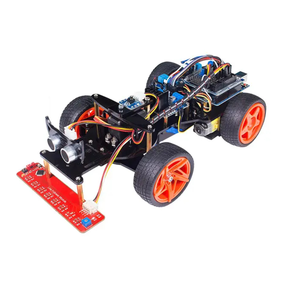
About the Smart Car Kit V2.0 for Arduino
This smart car can go forward and backward, and turn left and right. Controlled by the
SunFounder Uno board, it can realize IR remote control, line following, hand following,
obstacle avoiding, etc.
This car kit is a great platform for you to get started with robotics. After assembling the car
based on the instructions in this booklet, you will learn how to operate the smart car through
6 experiments corresponding to the aforementioned movements. Furthermore, you can
extend more functions or build your own robot based on what's learnt.
Note:
Go to LEARN -> Get Tutorials -> Smart Car Kit V2.0 for Arduino on our website
www.sunfounder.com
carefully before experiment. You are suggested to follow this guide to assemble the smart
car model and carry out each experiment taking the wiring steps with diagrams. Then, with
the knowledge needed, you may be able to DIY another car!
Free Support
If you have any TECHNICAL questions, add a topic under
website and we'll reply as soon as possible.
For NON-TECH questions like order and shipment issues, please
service@sunfounder.com. You're also welcomed to share your projects on FORUM.
Preface
to view the related code and other materials. Please read this manual
www.sunfounder.com
for more!
FORUM
section on our
send an email to
Advertisement
Table of Contents

Subscribe to Our Youtube Channel
Related Manuals for SunFounder Smart Car Kit V2.0


Summary of Contents for SunFounder Smart Car Kit V2.0
- Page 1 Note: Go to LEARN -> Get Tutorials -> Smart Car Kit V2.0 for Arduino on our website www.sunfounder.com to view the related code and other materials. Please read this manual carefully before experiment.
-
Page 2: Table Of Contents
Introduction to the Smart Car V2.0 for Arduino ..............7 Get Started ..........................8 Arduino ..........................8 Description ........................8 Arduino Board – SunFounder Compatible ............8 Install Arduino IDE ...................... 9 Add Libraries ......................12 Sensor Shield ........................13 Motor Driver Module ...................... - Page 3 Servo + Chassis + Battery Holder .................. 30 Adjust the Servo ......................34 Chassis + Deflecting Plate .................... 36 Chassis + Driven Wheels ....................37 IR Receiver + Ultrasonic + Line Follower ..............40 Other PCB Assembly ...................... 41 Circuit Building ........................ 42 Experiments ...........................
-
Page 4: Components List
Components List Acrylic Plate... -
Page 5: Mechanical Fasteners
Mechanical Fasteners Component Name Qty. M1.5*8 Screw M3*12 Countersunk Screw M3*6 Screw M3*8 Screw M3*10 Screw M3*28 Screw M4*10 Screw M4*20 Screw M3*10 Copper Standoff M3*13 Copper Standoff M3*25 Copper Standoff M3*30 Copper Standoff M3*35 Copper Standoff M4*30 Copper Standoff M1.6 Nut M3 Nut M4 Nut... -
Page 6: Power Accessories
F694ZZ Flange Bearing Power Accessories Component Name Qty. Tower Pro MG995 Micro Servo Gear Motor Driven Wheel Driving Wheel Electronic Accessories Component Name Qty. SunFounder Uno... - Page 7 Sensor Shield DC Motor Driver Module Step-down DC-DC Converter Module Switch Module HC-SR04 Ultrasonic Module Line Follower Module IR Receiver Module...
-
Page 8: Tools
IR Remote Controller 18650x2 Battery Holder Ribbon (13cm) USB Data Cable (1m) 12cm Male-to-Male Jumper Wire 10cm Male-to-Female Jumper Wire 10cm Female-to-Female Jumper Wire 25cm 3-pin Anti-reverse Cable 25cm 4-pin Anti-reverse Cable Tools Component Name Qty. Cross Screwdriver Cross Socket Wrench... -
Page 9: Self-Provided Components
Heat Shrink Tube Self-provided Components The following components are not included in this kit. Component Name Qty. 18650 3.7V Rechargeable Li- ion Battery Note: You are recommend to use 18650 batteries without a protective board. Otherwise, the car may be cut power and stop running because of the overcurrent protection of the protective board. -
Page 10: Introduction To The Smart Car V2.0 For Arduino
DC-DC converter module, switch module, ultrasonic ranging module, photosensitive module, obstacle avoidance module, and line follower module. Different modules are used to achieve corresponding functions. And the car is controlled by SunFounder Uno board. Next let's first check these modules in detail. -
Page 11: Get Started
So you can just download the Arduino IDE, upload the sketches (i.e. the code files) to the board, and then you can see experimental phenomena. For more information, refer to http://www.arduino.cc. Arduino Board – SunFounder Compatible In this kit, the SunFounder Uno R3 board is used and it is completely compatible with Arduino Uno Board. -
Page 12: Install Arduino Ide
Install Arduino IDE The code in this kit is made based on Arduino, so you need to install the IDE first. Skip it if you have done this. Step 1: Go to the arduino.cc website and click Software. On the page, check the software list on the right side under Download the Arduino Software. - Page 13 Next. Click Browse to choose the installation path or enter a directory at the Destination Folder. Click Install. The following interface will show up. (After the installing progress bar goes to the end, the Close button may be enabled for some PC. Just click it to complete the installation.)
- Page 14 Then a prompt appears. Select Always trust software for "Adafruit Industries" and click Install. Select Always trust software for "Arduino srl" and click Install. After the installation is done, click Close. Then an Arduino icon will appear on the desktop:...
-
Page 15: Add Libraries
Add Libraries 1) Select Sketch -> Include Library -> Add ZIP Library. 2) Find the file MsTimer2.zip under Smart Car V2.0 for Arduino\Code\Library. Click Open. 3) Similarly, IRromte.zip NewPing.zip under Smart V2.0 Arduino\Code\Library to library. 4) Then you'll be prompted by Library added to your libraries. -
Page 16: Sensor Shield
Sensor Shield It is convenient to place components on a breadboard. However, you need to have some electronic foundation to build various kinds of circuit. By using this sensor shield, you only need to wire components to the shield with some jumper wires, and then you can build your own project quickly. - Page 17 Its schematic diagram is as shown below: note that VCC only supplies power to the devices connected to D2 (hooked to the black servo) and D3. Other components are powered by...
-
Page 18: Motor Driver Module
Motor Driver Module The motor driver module is used to drive two motors to rotate. The driver chip used here is L298N. Its schematic diagram is as shown below:... - Page 19 L298N is a high voltage, large current driver chip manufactured by ST, which uses a 15-pin package. Its main features are as follows: • High operating voltage, which can be up to 40 volts. • Large output current - the instantaneous peak current can be up to 3A. •...
-
Page 20: Step-Down Dc-Dc Converter Module
The driver module can drive two motors. The enable terminals ENA and ENB are effective at high level. The control mode (high/low level) and state of motor A are as shown below: State of Motor A Stop Brake Rotate clockwise Rotate counterclockwise Brake If you want to regulate the speed of motor A by PWM, you need to set IN1 and IN2, confirm... - Page 21 The corresponding schematic diagram: The LM2596 regulator is a monolithic integrated circuit ideally suited for easy and convenient design of a step−down switching regulator (buck converter). It is capable of driving a 3.0A load with excellent line and load regulation. It is internally compensated to minimize the number of external components to simplify the power supply design.
-
Page 22: Switch Module
Its pin functions are as shown below: Name Description This is the positive input supply for the IC switching regulator. A suitable input by pass capacitor must be present at this pin to minimize voltage transients and to supply the switching currents needed by the regulator. -
Page 23: Ultrasonic Module Hc-Sr04 Distance Sensor
(a) When the button is NOT PRESSED (b) When the button is PRESSED Ultrasonic Module HC-SR04 Distance Sensor The ultrasonic ranging module HC-SR04 provides 2cm-700cm non-contact measurement function, and the ranging accuracy can reach 3mm. Stable signal can be ensured within 5m, and signal gradually fades beyond 5m till disappearing at 7m position. -
Page 24: Line Follower Module
ultrasound at 40 kHz and raise its echo. The echo is a distance object that is pulse width and the range in proportion .You can calculate the range through the time interval between sending trigger signal and receiving echo signal. Thus, uS / 58 = centimeters or uS / 148 =inch;... -
Page 25: Ir Receiver Module
This module is an infrared tracking sensor one that uses a TRT5000 sensor. The blue LED of TRT5000 is the emission tube and after electrified it emits infrared light invisible to human eye. The black part of the sensor is for receiving; the resistance of the resistor inside changes with the infrared light received. - Page 26 circle continuously like DC motor. The servo enables you to easily rotate an object in a certain angle, so it is widely used in model planes and robot joints. Only the MG995 SG90 Micro Servo is used in this kit, which is assembled on the front chassis of the car for steering structure.
-
Page 27: Car Assembly
Car Assembly Front Wheels Fasten the bearing, the following acrylic plates and driven wheel with an M4*20 screw and an M4 self-locking nut. Tighten the screws with the Cross Socket Wrench and the Cross Screwdriver. After assembly, it is as shown below: Do not over tighten the nuts so that the wheel can spin smoothly. -
Page 28: Deflecting Plate + Front Wheels
Deflecting Plate + Front Wheels Fasten the following acrylic plates and the assembled front wheel with M3*8 screws and M3*13 copper standoffs. And fasten an M3*8 screw and an M3*35 copper standoff to the smaller acrylic plate. After assembly, it is as shown below:... -
Page 29: Deflecting Plate + Rocker Arm
Connect another front wheel, as shown below: Note: After assembly is done, rotate the two wheels. If they cannot spin smoothly, loosen the M4 nuts with the wrench and the screwdriver. Deflecting Plate + Rocker Arm Fasten the following rocker arm of the SG90 servo to the deflecting plate with servo screws. -
Page 30: Rear Lower Plate + Rear Wheels
After assembly, it is as shown below: Note: The screw is quite sharp at the end, so be careful to assemble in case of getting hurt. Rear Lower Plate + Rear Wheels Assemble the following acrylic plates together. After assembly, it is as shown below:... - Page 31 Fasten the following acrylic plates and gear motor with M3*28 screws and M3 nuts. Assemble the driving wheel to the motor. After assembly, it is as shown below: Connect the other driving wheel, as shown below:...
-
Page 32: Deflecting Top Plate
Deflecting Top Plate Fasten the following acrylic plates with an M3*10 screw and an M3 self-locking nut. Tighten them with the cross wrench and the screwdriver (do not over tighten them). After assembly, it is as shown below: Do not over tighten the screws so that the acrylic plate can move smoothly. Mount the IR Receiver module with M3*8 screws and M3 nuts After assembly, it is as shown below:... -
Page 33: Servo + Chassis + Battery Holder
Servo + Chassis + Battery Holder Fasten the following acrylic plates, the chassis and the servo with M4*10 screws, M4 nuts and M4*30 copper standoffs. Note: You can tell the bottom and upside of the Chassis according to the holes distribution. Looking at the upside, sparse holes are on your right side... - Page 34 After assembly, it is as shown below: Fasten the acrylic plate for wire organizing to the chassis with an M3*10 screw and an M3 nut. After assembly:...
- Page 35 Connect similarly the other 3 acrylic plates symmetrically. Fasten the chassis with M3*8 screws and M3*10 copper standoffs. 10. After assembly, it is as shown below.
- Page 36 11. Cross the ribbon through the following acrylic plate. Please note that one side of the ribbon should be longer and the other is shorter. With the ribbon, you can remove the batteries easily. Also you can skip this step. 12.
-
Page 37: Adjust The Servo
Adjust the Servo 1) Connect the servo to the pin 2 of the sensor shield, and the wiring should be as shown below: Power Source Red to + Black to - Servo Brown to GND Red to VCC Orange to Signal (pin2) Servo Power + to VCC... - Page 38 2) Connect the SunFounder Uno board to your computer via a USB cable. Open the file Car_1_Forward.ino under the path Smart Car V2.0 for Arduino\Code\Car_1_Forward. Before uploading the sketch to the board, you need to select the right Board and Port through Tools ->...
-
Page 39: Chassis + Deflecting Plate
Chassis + Deflecting Plate Keep the servo power on, fasten the following acrylic plates with M3*8 screws and servo screw packaged with the servo among the shorter ones in black. Note: The central vertical lines of the Chassis and Deflecting Plate should be perpendicular, otherwise the front wheel will not be able to go straight as you control. -
Page 40: Chassis + Driven Wheels
The bottom view: Now, you can remove the servo wires. Chassis + Driven Wheels Fasten the Driven Wheels with M3*8 screws and M3*25 copper standoffs. - Page 41 Fasten the Driven wheels and Chassis with M3*8 screws. After assembly, it is as shown below: Mount the following acrylic plate on the car with M3*10 screws and M3 nuts.
- Page 42 After assembly, it is as shown below: Then assemble the ultrasonic fixing plate to the car with an M3*10 screw and M3 nut. After assembly, it is as shown below:...
-
Page 43: Ir Receiver + Ultrasonic + Line Follower
IR Receiver + Ultrasonic + Line Follower The ultrasonic module with M1.5*8 screws and M1.6 nuts, while the line follower with M3*8 screws and M3*30 copper standoffs. After assembly, it is as shown below:... -
Page 44: Other Pcb Assembly
Other PCB Assembly Assemble the DC Motor Driver Module, the Switch Module, the Step-down DC-DC Converter Module, and the SunFounder Uno board with M3*6 screws, and then plug the sensor shield into the Uno board, as shown below: The assembly should be like this:... -
Page 45: Circuit Building
The top view: Circuit Building 1) Connect the motor driver module and sensor shield: Motor Driver Module Sensor Shield INT1 INT2 INT3 INT4... - Page 47 2) Connect the motor driver module and two motors: Note: Please pay attention to that diagram. Each gear motor has two wiring terminals. You should wire them correctly. The wiring will affect the rotational direction of the gear motors. If you do not know how to distinguish, you can try wiring them randomly first.
- Page 49 4) Connect the step-down DC-DC converter module and switch module: Note: The two pins of the battery holder should not be in contact; otherwise it will cause a short circuit and the battery will be burnt. 5) Connect the IR receiver module and the sensor shield: IR Receiver Module Sensor Shield SIG (yellow)
- Page 50 The wiring connection is shown as below: 6) Connect the line follower module and the sensor shield: Line Follower Module Sensor Shield GND (black) VCC (red) SDA (yellow) A4 (SDA) SCL (white) A5 (SCL)
- Page 51 The wiring connection is shown as below: 7) Connect the ultrasonic module and the sensor shield: Ensure it's powered off, insert a 4-pin anti-reverse cable to the ultrasonic module, and connect the pins as follows: Note: Pay attention to the wires. The anti-reverse cable’s red and black wires do NOT connect to the anode and cathode!!! HC-SR04 Ultrasonic Module Sensor Shield...
- Page 52 After the assembly and circuits are finished, if you feel the wires are too messy, you may wrap them with the heat shrink tubing so the car can look more adorable with neat wiring. Now let's get started!
-
Page 53: Experiments
Change the rotational angle by sketch to make the car turn. Experimental Procedures Connect the SunFounder Uno board to your computer. Upload the sketch under the path Smart Car V2.0 for Arduino\Code\Car_2_Turn, and then remove the USB cable. Press down the button on the switch module, and the car will start running. -
Page 54: Experiment 3 Ir Remote Control
Experimental Procedures Connect the SunFounder Uno board to your computer via a USB cable. Upload the sketch under the path Smart Car V2.0 for Arduino\Code\ Car_3_Remote, and then remove the USB cable. -
Page 55: Experiment 4 Line Following
Experimental Procedures Connect the SunFounder Uno board to your computer. Upload the sketch under the path Smart Car V2.0 for Arduino\Code\Car_4_LineFollowing, and then remove the USB cable. Pressed the button on the switch module. - Page 56 2. If the front wheels do not turn when you place the car above the black lines, but it does when the module is tilt closer to the line, in other words there signal of black line detection is too weak, just adjust the potentiometer below to try.
-
Page 57: Experiment 5 Hand Tracking
Experiment 6 Obstacle Avoidance The wiring for this experiment is based on Experiment 5, so after the last experiment, just turn it off. Connect the SunFounder Uno board to your computer with a USB data cable. Upload... - Page 58 the sketch under Smart Car V2.0 for Arduino\Code\Car_6_AvoidObstacle, and then remove the USB cable. Principle Experimental The principle of this experiment is similar to that of experiment 5, and the difference is when it detects an obstacle 30cm ahead, it will turn right to avoid. Note: DO NOT increase the car’s speed too much, in case that the sensor in the front may be damaged due to great inertial effect upon stop.
- Page 59 All contents including but not limited to texts, images, and code in this manual are owned by the SunFounder Company. You should only use it for personal study, investigation, enjoyment, or other non-commercial or nonprofit purposes, under the related regulations and copyrights laws, without infringing the legal rights of the author and relevant right holders.
Need help?
Do you have a question about the Smart Car Kit V2.0 and is the answer not in the manual?
Questions and answers