Table of Contents
Advertisement
About SunFounder
SunFounder is a technology company focused on Raspberry Pi and Arduino open source
community development. Committed to the promotion of open source culture, we strive to
bring the fun of electronics making to people all around the world and enable everyone to
be a maker. Our products include learning kits, development boards, robots, sensor modules
and development tools. In addition to high quality products, SunFounder also offers video
tutorials to help your own project. If you have interest in open source or making something
cool, welcome to join us! Visit www.sunfounder.com for more!
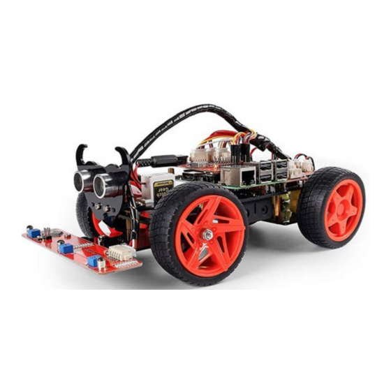
About the PiCar-S
The
PiCar-S
is a cool smart car that can work with Raspberry Pi model B+, 2 model B and 3
model B. Equipped with three sensor modules including ultrasonic obstacle avoidance, light
follower, and line follower, you can better learn the programming on how to control the car.
In this manual, we will show you how to build the PiCar-S via description, illustrations of physical
components, in both hardware and software respects. You will enjoy learning how all this work.
You may visit our website
user manual on
LEARN -> Get Tutorials
code on our page of github.com at
https://github.com/sunfounder/SunFounder_PiCar-S
You are welcome to pull requests and issue posts on our page on Github.
Free Support
If you have any TECHNICAL questions, add a topic under
and we'll reply as soon as possible.
For NON-TECH questions like order and shipment issues, please
service@sunfounder.com.
Preface
www.sunfounder.com
and watch related videos under
You're also welcomed to share your projects on FORUM.
to download the related code and view the
FORUM
VIDEO,
or clone the
section on our website
send an email to
Advertisement
Table of Contents

Subscribe to Our Youtube Channel
Related Manuals for SunFounder PiCar-S


Summary of Contents for SunFounder PiCar-S
- Page 1 In this manual, we will show you how to build the PiCar-S via description, illustrations of physical components, in both hardware and software respects. You will enjoy learning how all this work.
-
Page 2: Table Of Contents
Contents Components List ............................1 Acrylic Plates ............................1 Servo Accessories ..........................2 Mechanical Fasteners .........................2 Wires .................................3 PCB ................................4 Other Components ..........................5 Tools ................................6 Introduction ..............................7 Building the Car ............................7 Fixing Rear Wheels ..........................7 Upper Plate ............................10 Battery Holder ............................. 11 Rear Wheels (Driving) ........................ - Page 3 Robot HATS ............................. 57 PCA9865 ............................58 TB6612 .............................. 59 Line Follower Module ........................59 Light Follower Module ......................... 60 Ultrasonic Obstacle Avoidance Module ................61 SunFounder SF0180 Servo ......................61 WiFi Adapter ..........................62 DC Gear Motor ..........................62...
-
Page 4: Components List
Components List Acrylic Plates Upper Plate x 1 Hex Front Wheel Fixing Plate x 4 Front Half Chassis x 1 TF Card Guard x 1 Motor Support x 4 Back Half Chassis x 1 Bearing Shield x 4 Ultrasonic Connector x 1 Steering Linkage x 1 Ultrasonic Support x 1 Steering Connector x 2... -
Page 5: Servo Accessories
Servo Accessories The following three parts will be used in the servo package: 1. Rocker Arm 2. Rocker Arm Screw 3. Rocker Arm Fixing Screw Mechanical Fasteners Name Component Qty. M2x8 Screw M2.5x6 Screw M3x8 Screw M3x8 Countersunk Screw M3x10 Screw M3x30 Screw... -
Page 6: Wires
M4x25 Screw M2 Nut M2.5 Nut M3 Nut M4 Self-locking M2.5x8 Copper Standoff M3x25 Copper Standoff 4x11x4 F694ZZ Flange Bearing Wires 100mm HX2.54 5-Pin Jumper Wire 50mm HX-2.54 4- Pin Jumper Wire 50mm HX-2.54 2- Pin Jumper Wire 100mm HX-2.54 2-Pin Jumper Wire 200mm HX2.54... -
Page 7: Pcb
200mm HX2.54 3-Pin Jumper Wire Robot HATS PCA9685 PWM Driver TB6612 Motor Driver 5-CH Line Follower Module... -
Page 8: Other Components
Ultrasonic Obstacle Avoidance Module Light Follower Module Other Components 2x18650 Battery Holder DC Gear Motor SunFounder SF0180 Servo Rear Wheel... -
Page 9: Tools
Front Wheel USB Wi-Fi Adapter Ribbon (30cm) Tools Cross Screwdriver Cross Socket Wrench M2.5/M4 Small Wrench M2/M3 Small Wrench... -
Page 10: Introduction
Introduction is a SMART SENSOR car robot based on Raspberry Pi, which comes with three sensor modules, including the light follower, line follower and ultrasonic obstacle avoidance. With these modules, this smart car is capable of some simple automatic actions. Thus, you can learn some basics of programming in Python to control the car with these sensors. - Page 11 Assemble the two motors with four M3x30 screws and M3 nuts. Pay attention to place the motors with wires inward, providing convenience for connecting the circuit. Place wires inwards...
- Page 12 Insert four M3x25 copper standoffs through the acrylic plate into four M3 nuts as shown below: So now this part is completed. You can put it aside for now.
-
Page 13: Upper Plate
Upper Plate Mount the M2.5x8 copper standoffs and M2.5 nuts into the upper plate first. There are three PCBs to be installed onto the plate and four copper standoffs are needed for each. So here 12 holes should be used, marked with cross as shown below: Assemble the M2.5x8 copper standoffs and M2.5 nuts as shown below. -
Page 14: Battery Holder
Battery Holder Turn the Upper Plate upside down. Cut the ribbon into two halves. Thread them through the holes on the plate. Pay attention to the direction and leave one end longer out of the plate for each to remove the battery easily later. - Page 15 Fasten the battery holder with two M3x8 countersunk screws and two M3 nuts: pay attention to the direction of battery holder’s wire.
-
Page 16: Rear Wheels (Driving)
Rear Wheels (Driving) Mount the assembled rear wheel driving part onto the Upper Plate with four M3x8 screws:... - Page 17 Assemble the rear wheels: Align the rear wheels with the motor shaft, and rotate to insert them gently.
-
Page 18: Tf Card Guard
TF Card Guard Mount the TF Card Guard plate onto the side near the front wheel with an M3x10 screw and an M3 nut. First place the nut into the slot from the underneath, and then insert the screw into the nut through the plate. -
Page 19: Front Half Chassis
Front Half Chassis Assemble the Front Half Chassis with four M3x25 copper standoffs and four M3 nuts as shown below:... -
Page 20: Front Wheels
Wheels Front Insert an M4x25 screw through a Flange Bearing (pay attention to the direction – the flange near the cap of the screw), a Steering Connector, 2 Bearing Shields, 2 Hex Front Wheel Fixing Plates, and a front wheel, into an M4 Self-locking Nut (note the direction) as shown below: Flange The Self-locking Nut should be screwed tight enough. -
Page 21: Steering Part
Part Steering Take out the Rocker Arm and the Rocker Arm Screw (the longer one): Connect the Steering Linkage and the rocker arm with the screw. Note: Insert it into the first hole of the arm (as indicated by the arrow below) which is the farthest from the gears. - Page 22 Mount the steering servo to the Upper Plate with two M2x8 Screws and two M2 nuts (pay attention to the direction of the servo wires): Till here the car assembly is mostly done. But don’t hurry to assemble the front wheels, because the servo has not been adjusted yet.
-
Page 23: Pcb Assembly
PCB Assembly Assemble the Raspberry Pi (TF Card inserted) with four M2.5x8 copper standoffs, then plug the Robot HATS onto it, and fix the PCA9685 PWM Driver, the TB6612 Motor Driver and the Robot HATS with twelve M2.5x6 screws. Robot HATS PCA9685 TB6612 Raspberry Pi... -
Page 24: Circuits Building
Circuits Building Connect the PWM CONTROL of the Robot HATS with the PCA9685 PWM Driver, and the TB6612 CONTROL with the TB6612 Motor Driver. Then the Left Motor and the Right Motor of the TB6612 to two motors, and the Motor PWM with the No. - Page 25 So now the circuit boards are all installed onto the car and the wiring is done. But still you're not ready to adjust the servo yet. First you need to complete some software installation.
-
Page 26: Software Installation
You can find the source code in our Github repositories. Download the source code by git clone: clone --recursive https://github.com/sunfounder/SunFounder_PiCar-S.git pi@raspberrypi:~ $ git clone --recursive https://github.com/sunfounder/SunFounder_PiC ar-S.git Cloning into 'SunFounder_PiCar-S'... remote: Counting objects: 162, done. remote: Total 162 (delta 0), reused 0 (delta 0), pack-reused 162 Receiving objects: 100% (162/162), 61.98 KiB | 36.00 KiB/s, done. -
Page 27: Go To The Code Directory
Cloning into 'example/SunFounder_Line_Follower'... remote: Counting objects: 8, done. remote: Total 8 (delta 0), reused 0 (delta 0), pack-reused 8 Unpacking objects: 100% (8/8), done. Checking connectivity... done. Submodule path 'example/SunFounder_Line_Follower': checked out '9560e7adbb52a883d438b 78de90d185fc168fed5' Cloning into 'example/SunFounder_Ultrasonic_Avoidance'... remote: Counting objects: 24, done. remote: Total 24 (delta 0), reused 0 (delta 0), pack-reused 24 Unpacking objects: 100% (24/24), done. -
Page 28: Adjust The Servo To 90 Degrees
2. Install python-smbus sudo apt-get install python-smbus -y 3. Install the PiCar module https://github.com/sunfounder/SunFounder_PiCar.git clone --recursive SunFounder_PiCar python setup.py install 4. Enable I2C Edit the file /boot/config.txt sudo nano /boot/config.txt The "#" in front of each line is to comment the following contents which does not take effect in a sketch. -
Page 29: Build The Rest Of The Car
immediately, but all servos will keep at 90 degrees. You can continue the rest assembly. Warning: After power is on, a short circuit may happen because the exposed contacts of the PCB may be touched by conductive objects like screw or screwdriver. If it occurs, please remove the conductor immediately or unplug the power as quickly as you can. - Page 30 Take out the assembled front wheels and the Upper Plate, and mount the wheels onto the Upper Plate carefully: insert one bulge of the Steering Connector at either wheel into the hole on the Steering Linkage plate, and another bulge into the Upper Plate, and similar with the other wheel.
-
Page 31: Configuration
Now, the whole assembly, the wiring and code are all DONE! Congrats! Enjoy the satisfaction and thrill. Configuration Remember the commands to adjust the servo to 90 degrees previously? Now, let’s talk about the other two commands. The second command front-wheel-test is used to test whether the front wheels can turn flexibly after assembly. - Page 32 ^Cturn_straight You may find the direction of the front wheels is not facing exatly front when they are in the straight status (they will return to the status anytime the front wheels program stops running). If there is an obvious deviation from the middle line of the front chassis, remove the servo and servo-install again;...
- Page 33 After changing the value of turning_offset, press Ctrl + O to save the changes, and press Ctrl + X to exit. Run the command picar servo-install to check the front wheel’s status. pi@raspberrypi:~/SunFounder_PiCar/picar $ picar servo-install pi@raspberrypi:~/SunFounder_PiCar/picar $ If the front wheels is still not facing the exact front, you may need to edit the file config for a couple of times.
- Page 34 Press Ctrl + O to save the changes, and press Ctrl + X to exit. Run the command picar rear- wheel-test again to check whether the rear wheels are rotating in accordance with the command. Copy config to the directory example under PiCar-S. pi@raspberrypi:~/SunFounder_PiCar/picar $ cp config ~/SunFounder_PiCar-S/example...
-
Page 35: Arming The Car
Now let’s turn the PiCar into the PiCar-S. What exactly is the PiCar-S? ------- We arm the PiCar with some sensors, which endow the car with the ability to collect and process the data. The sensor modules... -
Page 36: Ultrasonic Obstacle Avoidance
Raspberry Pi that can calculate the distance from the obstacle. The Pi will send a command to adjust the front wheels and rear wheels direction and rotation to control the PiCar-S walk away from the obstacle if there is one. - Page 37 Step 2. Wiring Robot HATS Connect the ultrasonic obstacle avoidance to with a 3-pin anti-reverse cable as shown below. Ultrasonic Obstacle Avoidance Robot HATS 3.3V Test for Ultrasonic Obstacle Avoidance First, test the ultrasonic obstacle avoidance module before applying. Get into the directory example: ~/SunFounder_PiCar-S/example/ Run the test code: python...
-
Page 38: Software Flow
Get on the road! The PiCar-S starts running now. Just place the car on the ground. It will follow the program to turn when it detects an obstacle; if the obstacle is too close, it will move backwards, and turn left/right. - Page 39 The ultrasonic module returns a digital value, i.e., High or Low level, and the interval time between two levels returned can be converted to the distance to the obstacle. Thus, we call the time module in Python for timing here. The formula to calculate the distance is written in the ultrasonic module’s driver.
-
Page 40: Code Explanation
Turn Backward Forward Code Explanation ua = Ultra_Sonic.UltraSonic_Avoidance(17) Create an object ua of a UltraSonic_Avoidance class in the Ultra_Sonic module. The number in the round bracket is the initial parameter, which represents the pin number the SIG of the module is connected to. Since the BCM naming method is applied, the corresponding pin on the Raspberry Pi is #17. -
Page 41: Light Following
larger the number (within the range 0-100) is, the faster the wheel rotates. fw.turn(angle), function in the back_wheels, to set the turning angle. The angle is 90 when the car moves straight forwards; reduce the number to turn left, and increase it to turn right. fw.turn_straight(), making the front wheels return to the angle of moving straight forwards. -
Page 42: Procedures
Procedures Step 1 Assembly Connect the light follower to the Sensor Connector with M3*10 screws and M3 nuts, and then assemble them to the car with two M3*10 screws and two M3 nuts. You're suggested to hold the nuts underneath with your fingers. Step 2 Wiring Connect the light follower to the Robot HATS with a 5-pin anti-reverse cable as shown below. - Page 43 Test for Light Follower Let’s test the light follower first. Get into the directory example ~/SunFounder_PiCar-S/example/ Run the test code python test_light_module.py pi@raspberrypi:~ $ ~/SunFounder_PiCar-S/example/ pi@raspberrypi:~/SunFounder_PiCar-S/example $ python test_light_module.py [237, 233, 237] [236, 230, 236] [232, 238, 246] [237, 240, 251] [145, 175, 200] [228, 234, 74] [219, 226, 23]...
-
Page 44: Software Flow
So just place the car in an open field and wait. Picar-S follows light When the calibration is done, the car will stop temporarily. Shine a flashlight on the light follower module, and the car will just follow the light spot as you moves it. - Page 45 2. Here write two main functions/modules including light following calibration and light following in the main program. Start Calibration Take the min function values of each sensor as Calibratio Calibrate reference n function Create lists for collected values Upload trigger threshold values to Light Check light...
- Page 46 The light follower includes three phototransistors, thus its status list is composed of three elements which represent 8 statuses (based on permutation and combination). And here we need to set related responses to these statuses. The three elements show the status of the three probes: 1 represents light detected, and 0, for none.
-
Page 47: Code Explanation
angle and small-angle turning. If the light is at the central left side (status [1,1,0]), we should apply a small-angle turning; if the light is at the edge of the left side (status [1,0,0]), we should apply a large-angle turning. Code Explanation To understand the code, take the software subflows above for reference. -
Page 48: Line Following
bw.set_speed(forward_speed) Here we need two functions for rear wheels. The first function is to control the rotating direction as forward (the function for backwards is bw.backward()). The second one is to set the rotating speed of the wheels; the parameter is the speed value (range: 0-100). The bigger the parameter is, the faster the wheel rotates. - Page 49 Step 2 Wiring Connect the line follower module to the Robot HATS with a 4-pin anti-reverse cable as shown below. Line Follower Robot HATS 3.3V Test for Line Follower Get into the directory example: ~/SunFounder_PiCar-S/example Check whether any i2c device is recognized or not via i2c-tools sudo i2cdetect –y pi@raspberrypi:~ $...
- Page 50 Starts Running! When the module calibration is all completed, we can run the car then. Place the PiCar-S with probes above the black line on the white board, and then it will go forward following the line...
- Page 51 itself. How to make a track for line following To make a track for the car to follow a black line, you need to prepare the following materials: A large sheet of paper, a roll of black tape (as black lines), a hard card board (the size depending on the size of the track) or a flat surface like the floor or desk.
-
Page 52: Software Flow
Software Flow Considering the interference of negative environment factors, we need to calibrate the line follower sensor before actual use. Here two main functions including the line follower calibration and line following are included in the main program. Subflow of Line Follower Calibration Function When we run the line follower configuration, we will start from white color, then black color, which is more like the upper limit and lower limit of the sensor. - Page 53 Line follower calibration function Prompt user to Prompt user to calibrate for calibrate for white color black color Delay for user to Delay for user to place the sensor place the sensor above white surface above black line Take the average value for each sensor Sensor reads the...
- Page 54 In the line following function, we set the turning angle of the servo in different levels according...
- Page 55 to the detection results of the probes. If the line in front of the car is detected as a small curve, then the car will turn a small angle; if it is a big one, the car will turn a large angle. Thus, here we set four angle-turning constants: a_step, b_step, c_step, and d_step.
-
Page 56: Code Explanation
response program to let the car move backwards in the opposite direction (3), and then turn back to the original direction until a black line is detected again and move forward (4). Code Explanation The logic of the code is just as shown in the flow chart above. Three Python modules... -
Page 57: Combination
Combination So, this smart car now is smart in three separate features. But, you think only one sensor module is not enough? Try to combine those sensor modules in one! Here we can show you an experiment - light following with obstacle avoidance for referece. When the car runs with the light follower, sometimes it may crash into obstacles when following the light, and it’s not quite convenient to let the car move back (though we've set the car to move backward if the array is [1,0,1], it’s hard to acquire these values since the the car is... - Page 58 Start Run light follower Calibration calibration function Detect obstacles avoid_flag == 1 Else avoid_flag == 2 If an obstacle If close to an If no obstacle found, detected, move obstacle, turn away keep following light backwards Run light Light following following subfunction program...
- Page 59 at the left side if the spot is , it will return light_flag = at the back if the spot is , it will return light_flag = no light spot is detected, it will return light_flag = The main program main() will run the corresponding program according to avoid_flag...
-
Page 60: Appendix
Appendix Appendix 1: Modules Robot HATS Robot HATS is a specially-designed HAT for a 40-pin Raspberry Pi and can work with Raspberry Pi model B+, 2 model B, and 3 model B. It supplies power to the Raspberry Pi from the GPIO ports. -
Page 61: Pca9865
UART port: 4-wire UART port, 5V VCC, perfectly working with SunFounder FTDI Serial to USB. ○ TB6612 motor control ports: includes 3.3V for the TB6612 chip, 5V for motors, and direction ○ control of motors MA and MB; working with SunFounder TB6612 Motor driver. -
Page 62: Tb6612
TB6612 The TB6612 Motor Driver module is a low heat generation one and small packaged motor drive. Power and motor control port: includes pins for supplying the chip and the motors and ○ controlling the motors' direction PWM input for the motors: PWM signal input for adjusting the speed of the two motors ○... -
Page 63: Light Follower Module
The TCRT5000 infrared photoelectric switch adopts a high transmit power infrared photodiode and a highly sensitive phototransistor. It works by applying the principle of objects' reflecting IR light – the light is emitted, then reflected, and sensed by the synchronous circuit. Then it determines whether there exists an object or not by the light intensity. -
Page 64: Ultrasonic Obstacle Avoidance Module
SunFounder SF0180 Servo The SunFounder SF0180 Servo is a 180-degree three-wire digital servo. It utilizes PWM signal of 60Hz and has no physical limit – only control by internal software to 180 degrees at most. -
Page 65: Wifi Adapter
Electrical Specifications: Item V = 4.8V V = 6.0V Operating speed (no load) 0.12 Sec/60° 0.09 Sec/60° Running current (no load) 140 mA 200 mA Stall torque (locked) 2.0 kg-cm 2.5 kg-cm Stall current (locked) 520 mA 700 mA Idle current (stop) 5 mA 5 mA For more information, refer to SunFounder_PiCar-S/datasheet/SunFounder_SF0180.pdf in the... - Page 66 All contents including but not limited to texts, images, and code in this manual are owned by the SunFounder Company. You should only use it for personal study, investigation, enjoyment, or other non-commercial or nonprofit purposes, under the related regulations and copyrights laws, without infringing the legal rights of the author and relevant right holders.
Need help?
Do you have a question about the PiCar-S and is the answer not in the manual?
Questions and answers