Table of Contents
Advertisement
Quick Links
Advertisement
Table of Contents

Related Manuals for Digatron DT-40K


Summary of Contents for Digatron DT-40K
- Page 1 ENGINE MONITORING SYSTEMS DT-40K INSTRUCTION MANUAL...
-
Page 2: Table Of Contents
TABLE OF CONTENTS Introduction ................1 Sensor Installation ..............2 Electrical Interference ..............3 Power On...................4 Display Resolution ..............4 Monitoring and Recording............5 Ways to Begin Recording ............6 Information about Recording ..........6 Acknowledging Overlimit Condition ........7 Reset Lap and Event Number and Clear Memory ....7 Analyze Data ................8 Lap Times and Maximums............8 Detailed Review of a Lap ............9... -
Page 3: Introduction
Included with your instrument is a simple instruction sheet that allows you to quickly install and use your Digatron DT-40K. The instructions in this booklet are more detailed to help you learn all of the capabilities of your new instrument. -
Page 4: Sensor Installation
Sensor Installation (General) These instructions cover all the sensors that can be used with the DT-40K. Some may not pertain to your particular model. • Tach Sensor: Must be hooked up for instrument to work correctly. • Temperature Sensors: If not used, use a shorting plug. -
Page 5: Electrical Interference
• Be sure that all sensors are connected to the instrument, and that all connectors fit together snugly. Any functions not being used must have a plug on the pigtail. Please contact Digatron if the problem continues. -
Page 6: Power On
20 minutes. Setting Limits and Calibration Number Before using your DT-40K, be sure to set the operating limits for each input. Limits allow the instrument to give you a visual warning (the display flashes) if any of the inputs exceed their limit. -
Page 7: Monitoring And Recording
Monitoring and Recording When your instrument is powered on, it is monitoring your engine functions and ready to begin recording. The instrument will visually warn you, by flashing the display, if your engine exceeds any of it’s set limits. These limits allow you to avoid engine damage. You can make quick tuning adjustments to your engine that allow you to run safe and fast. -
Page 8: Ways To Begin Recording
Begin Recording There are three ways to begin recording data: 1. Starting the engine while the instrument is turned off, automatically starts the instrument and begins recording the Event. 2. Manually turn the instrument on with the Exit/Power button before the engine is started. -
Page 9: Acknowledging Overlimit Condition
Acknowledging an Overlimit Condition When one of the functions of your instrument exceeds it’s set limit, the instrument will display that function and flash the display. To return the instrument to the function that was displayed before the overlimit condition, press any button. Your engine may still be running over the set limit, but the instrument will not display that condition after you press a button. -
Page 10: Analyze Data
Analyze Data There are two ways to look at the recorded information: 1. View maximum readings and lap times for each lap. 2. Play the selected lap. Note: PRS (PReviouSly recorded data) is visible on the left side of the display during both of the above. -
Page 11: Detailed Review Of A Lap
Detailed Review of a Lap You can review all of the detailed information recorded for the lap that was selected in Laps. The information can be played back, for each function, in real time or stepped through in 0.1 second increments. •... -
Page 12: Appendix A: Sensor Installation
APPENDIX A: Sensor Installation (detailed) Tach Sensor Installation Our standard Tach sensor can be installed on both two and four cycle engines. For best results, keep the Tach sensor cable separated as much as possible from all other cables running to your instrument. Use a cable tie on the shrink tube, at the end of the green wire, to attach the sensor to the plug wire, keeping the end at least 2"... - Page 13 Standard Inductive Tach Sensor Installation Fig. 1a Example of standard installation Low Energy Ignition Inductive Tach Sensor Installation (Briggs) Fig. 1b Example of Briggs installation...
-
Page 14: Cht Sensor
CHT Sensor Installation Our standard CHT sensor is for air cooled engines only. For temperatures consistently above 450˚F we have a thermocouple type sensor. Remove the spark plug from the cylinder you wish to monitor and discard the plug washer. (see Fig. 2) Check the surface of the head around the spark plug hole for a smooth, flat finish to assure a good seal when the sensor is installed. -
Page 15: Beacon Receiver
Using A Beacon Transmitter (Optional) When using Digatron SMART beacons, multiple beacons can be on the track at once. Each SMART beacon can transmit one of 16 different signals. Your instrument treats all of these signals as lap signals. When the instrument encounters a beacon signal, it starts recording the race or it stops recording the current lap and begins a new one. -
Page 16: Manual Lap Switch
The DT-40K uses One AAA Battery (not included) The DT-40K can run, without a backlight, for 200 hours on one AAA battery. When using the backlight, one battery will power the instrument for 50 hours. With the front of the instrument facing you, remove the left end cap. Remove the battery from the holder. -
Page 17: Appendix B: Setting Limits
APPENDIX B: Setting Limits Limits should be set at levels that allow you to react to the visual warning before engine damage occurs. • Enter Set Limits: To enter Set Limits press . The display should now be flashing. • Change Number:To change the number being displayed press the or the button. -
Page 18: Cht
Cylinder Head Temperature Cylinder head temperatures (CHT) usually run in the 300˚F to 475˚F range. The best way to determine the correct temperature for your particular motor is to tune for proper plug or piston color and then observe what the head temperature is for various throttle settings and atmospheric conditions. -
Page 19: Appendix C: Button Functions
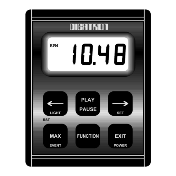
APPENDIX C: Button Functions Set Limits: Decreases the value of the limit being set. Hold this button down for the number to change faster. Pg. 15 Monitor/Record: Toggles the backlight on and off. Pg. 5 Laps: Finds previous lap’s data. Pg. 8 Playback: Causes the data to be played in reverse direction, while data is being played back. - Page 20 Powers on the instrument. Pg. 4 Set Limits: Press this button to exit Set Limits and return to Monitor/Record. Pg. 15 Monitor/Record: Powers off the instrument or stops recording data. It will only turn off the instrument if it is not recording and not receiving a Tach signal.
-
Page 21: Troubleshooting
Troubleshooting The following are explanations to some commonly asked questions. What are those letters on the side of my display? There are five annunciators that may be displayed on the left side of your display. (see Fig. 9) The most common ones represent the engine function being displayed at that time: CHT stands for Cylinder Head Temperature EGT stands for Exhaust Gas Temperature... - Page 22 Why does my instrument only record for 2 minutes? Your instrument will record for longer than 2 minutes, but your display has a limit to what it can show. The instrument has two resolution levels, high and low. • To change the resolution of your display, press the and the buttons at the same time, while in Monitor/Record mode.
-
Page 23: Repairs
Send your instrument and sensors so that we can check the complete system. Send repairs to: Digatron 8102 N. Freya St. Spokane, WA 99217 www.digatron.cc...
Need help?
Do you have a question about the DT-40K and is the answer not in the manual?
Questions and answers