Table of Contents
Advertisement
Quick Links
Advertisement
Table of Contents

Related Manuals for Painless Trail Rocker


Summary of Contents for Painless Trail Rocker
- Page 1 Trail Rocker Installation Instructions 2007-2010 Jeep Wrangler JK Dash Panel Trail Rocker For Installing Painless Part Number: 57002 Manual #90581 Painless Performance Products recommends you, the installer, read this installation manual from front to back before installing this harness.
- Page 3 E-Mail: painless@painlessperformance.com If you have any questions concerning the installation of this product, feel free to call Painless Performance Products' tech line at 1-800-423- 9696. Calls are answered from 8am to 5pm central time, Monday thru Thursday, 8am-4:30pm Friday, except holidays.
-
Page 4: Table Of Contents
FUSE/RELAY CENTER INSTALLATION SWITCH PANEL INSTALLATION SWITCH WIRING DOUBLING SWITCH CONTROL WIRES IGNITION SWITCH PIGTAIL INSTALLATION RELAY OUTPUT WIRES OPTIONAL: PAINLESS PART#: 57150 - WINCH CONTROL ADD-ON KIT OPTIONAL: WINCH PIGTAIL FINAL STEPS FUSE REPLACEMENT PAINLESS PERFORMANCE LIMITED WARRANTY AND RETURN POLICY... -
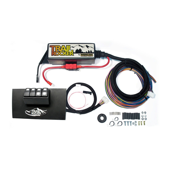
Page 5: Contents Of The Painless Kit
If you find that anything is missing or damaged, please contact the dealer where you obtained the kit or Painless Performance at (800) 423-9696. The Painless Trail Rocker Kit 57002 should contain the following: Fuse/Relay Center pre-installed to powder coated bracket ▪... -
Page 6: Tools Needed
TOOLS NEEDED This installation primarily requires only basic hand tools that may include, but are not limited to: 1. Wrench sets SAE and Metric 2. Ratchet sets SAE and Metric a. ¼” Drive w/ an extension is recommended for some tight areas of the install. b. -
Page 7: Fuse/Relay Center Installation
FUSE/RELAY CENTER INSTALLATION The following steps MUST be followed as they are printed. Do not move onto other parts of the installation out of sequence. CAUTION: BEFORE THE INSTALLATION OF THIS PRODUCT, DISCONNECT THE POWER FROM YOUR VEHICLE BY REMOVING THE BATTERY CABLES FROM THE BATTERY. - Page 8 Step 2: Use a flathead screwdriver to lightly pry the factory wiring and connector from the right side of the battery box. Then remove the black plastic retainers, so that the connector is easy to stow away later.
- Page 9 Step 3: After you remove the connector, “unlock” the red tab by using flathead screwdriver.
- Page 10 Step 4: With the tab unlocked unplug the connector. Step 5: Use a 10mm wrench socket to remove the battery tray mounting nut from the stud on the firewall.
- Page 11 Step 6: Locate the Fuse/Relay Center in your new. Remove and discard the black plastic retainers and flat washers securing the Fuse/Relay Center to its packaging. The retainers and washers are NOT used in installation.
- Page 12 Step 7: Remove the Fuse/Relay Center from the bracket. To do this remove the lid from the Fuse/Relay Center using a ∕ ” wrench or socket. Step 8: Once the cover is removed, notice the mounting bolts located below the relays.
- Page 13 Step 9: Use a #2 Stubby Philips-head screwdriver to hold the bolts in place while you remove the ¼” threaded, acorns nuts on the bottom of the unit with a ∕ ” wrench socket.
- Page 14 Step 10: With the Fuse/Relay Center removed locate the center hole on the bracket and a ¼”-20 stainless bolt. Insert the bolt into the center hole.
- Page 15 Step 11: Fasten the bracket to the Fuse/Relay Center using the ¼” threaded, acorns nuts you removed in Step 7.
- Page 16 Step 12: Position the Fuse/Relay Center mounting bracket over the factory firewall mounted stud, and hand-tighten the factory battery tray nut onto the firewall stud.
- Page 17 Step 13: Use the provided (1) ¼”-20 bolts, (1) flat washers, and nylon locking nuts to mount the Fuse/Relay Center mounting bracket to the factory battery tray as shown.
- Page 18 Step 14: Use a 10mm wrench socket to reinstall the factory battery tray nut to stud on the firewall, and secure the Fuse/Relay Center mounting bracket.
- Page 19 Step 15: Position (2) 1” Adel clamp over the Fuse/Relay Center control wires. Step 16: Mount the Adel clamps to the holes on the Fuse/Relay Center bracket using the supplied (2) ¼”-20 bolts, (2) flat washers, and (2) ¼” nylon locking nuts.
- Page 20 Step 17: Route the Fuse/Relay Center control wires across the firewall. Secure the control wires to the factory harness loom using the provided zip-ties. Remember, also, to reconnect the factory connector you unplugged in Steps 2-4. Step 18: On the driver side of the engine bay, locate the horn and remove it using a 10mm wrench or socket.
- Page 21 WARNING: MAKE SURE YOUR SYSTEM IS NOT CONNECTED TO THE BATTERY! THESE WIRES ARE HOT WHEN THE TRAIL ROCKER HAS POWER AND WILL SHORT THE SYSTEM OUT IF THEY TOUCH AS SEEN IN THE IMAGES BELOW. AGAIN, DO NOT RECONNECT THE...
- Page 22 Step 21: Carefully route the Switch Control wire connector through the pass-through. Step 22: Apply the provided rubber grommet over the Switch Control wires with the slit facing up.
- Page 23 Step 23: Push the rubber grommet into the firewall access hole as shown. Step 24: On the interior, remove the tape locate 12-pin connector shell in your parts kit. Then, connect the pinned wires from Fuse/Relay Center using the diagram below. NOTE: The diagram below shows the connector from the wire side.
- Page 24 Now, move to Step 25 on page 21 for the Switch Panel installation.
-
Page 25: Switch Panel Installation
SWITCH PANEL INSTALLATION Step 25: Now, move to the interior of the vehicle. In order to install the switch panel, you will need to reposition the center console. To do this, first, remove the 4 bolts holding the console in place using a T30 Torx driver. - Page 26 Step 26: Next remove the netted storage panel from the dash by using a pry tool, or carefully pulling on the netting.
- Page 27 Step 27: Remove the original metal retainer clips from the panel you just removed and attach them to your Trail Rocker Switch Panel.
- Page 28 Step 28: Now, install the Trail Rocker switch panel by routing the control wire plug through the center console as shown below.
- Page 29 Step 29: With the control wires routed through, position and clip in the new Trail Rocker switch panel. Press down firmly to ensure the panel locks in place at the bottom. Finally, reattach the center console.
-
Page 30: Switch Wiring
SWITCH WIRING The lighted rocker switches included in your kit are wired as shown in the diagram below. -
Page 31: Doubling Switch Control Wires
DOUBLING SWITCH CONTROL WIRES Steps 30 – 32 are optional and only for those who wish to control multiple functions for one switch. Provided in the kit are several piggyback terminals, like those shown below. These terminals provide you with two different options for doubling switch control wires. - Page 32 Step 31: Place on the piggyback terminal. Step 32: Take the power output wire and an additional wire from the Switch Control pigtail and connect them to the piggyback terminal.
-
Page 33: Ignition Switch Pigtail Installation
IGNITION SWITCH PIGTAIL INSTALLATION THESE STEPS ILLUSTRATE HOW TO HOOK UP YOUR TRAIL ROCKER TO IGNITION SWITCHED POWER AND ARE COMPLETELY OPTIONAL. IF YOU WANT TO OPERATE YOUR SWITCHES WITH A CONSTANT POWER (AS SHIPPED), SKIP STEPS 33 - 50 AND MOVE ON TO THE RELAY OUTPUT WIRES SECTION ON PAGE Step 33: Remove the panel below the steering column by carefully... - Page 34 Step 35: Locate the ignition switch connector and remove it. To do this, use a small flathead screwdriver to unlock the orange clip on the side of the connector.
- Page 35 Step 36: With the orange clip unlocked, squeeze the bottom of the connector and disconnect it. Step 37: Now, peel back the convoluted tubing covering the wires running to the ignition switch connector. Then, cut the Pink/White, 12V ignition wire about 2”...
- Page 36 Step 38: Unpin the factory ignition switched 12V wire. To do this, first, use a small screwdriver pick to remove the blue locking mechanism.
- Page 37 Step 39: With the blue lock removed, use a small screwdriver pick to depress the lock underneath the middle terminal. (Pin 3 = Ignition Switched 12V)
- Page 38 Step 40: With the terminal unlocked, pull the terminal out of the connector. Provided in your parts kit is a replacement ignition pigtail that will provide your Trail Rocker with ignition switched power while allowing you to terminate into the factory ignition switched 12V wire.
- Page 39 Step 41: Remove the driver side dash access panel and insert the new ignition pigtail thru the channel, to the center access, and route ignition pigtail towards the factory ignition switch connector.
- Page 40 Step 42: Now, re-pin the factory ignition switch connector (Pin with the new ignition pigtail. Step 43: With the ignition pigtail fastened, reinstall the blue locking mechanism.
- Page 41 Step 44: Now, strip the factory pink/white, 22-gauge wire ∕ ”. Once stripped, fold the copper wire in half to ensure a tight connection to the butt connector. Then, slide a piece of heat shrink over the factory wire and crimp it into the open end of the butt connector on the ignition pigtail.
- Page 42 Step 46: Reinstall the factory convoluted tubing over the factory wire. Step 47: Reinstall the factory ignition switch connector, and lock it into place.
- Page 43 Step 48: Now, connect the weather pack connector from the ignition pigtail to the weather pack connector on the switch control wires coming from the Fuse/Relay Center. (Note: for ease of installation you may want to unplug the Fuse/Relay Center’s switch control wire connector from the Switch Control Panel.) Step 49: If you do disconnect the Switch Control Panel from the Fuse/Relay Center’s switch control wire connector, reconnect...
- Page 44 Step 50: Reinstall the driver side access panel and then replace the metal bracket and plastic access panel beneath steering column.
-
Page 45: Relay Output Wires
RELAY OUTPUT WIRES Route these wires to the location of your components. Ensure to route them safely, and avoid high heat areas, moving parts, and sharp edges. Painless recommends using grommets for any wires passing through metal to avoid wearing through the wire insulation and causing arcing. Make sure any accessories and/or components you install are properly grounded. - Page 46 Step 51: Locate the relay output wire from the Fuse/Relay Center you wish to use. Then, locate the input wire on the accessory you are installing. Step 52: Double up the accessory’s input wire if necessary.
- Page 47 Step 53: Slide a piece of heat shrink from the included parts kit over the accessory wire. Then, use an un-insulated butt connector to crimp together the accessory wire with the relay output wire. Step 54: Secure the heat-shrink over the connection.
- Page 48 Step 55: Cap all unused relay output wires by crimping on the provided insulated wire caps. Then store the extra wires out of the way in the most convenient way possible.
-
Page 49: Optional: Painless Part#: 57150 - Winch Control Add-On Kit
These wires control the in and out functions of a winch when it is installed. These control wires can be connected to a winch switch (not provided in the kit). If you do not have a winch switch, Painless offers a Winch Control Add-on (Painless Part #: 57150, available online at www.painlessperformance.com). - Page 50 Step 56: Remove the switch control, power, and ground wires from the switch you are replacing with the Winch Control Add-on Kit. Then, locate the tabs located at the top and bottom of the switch. Step 57: These tabs lock the switch in place. To remove the switch, squeeze the tabs in and slide it out of the bracket.
- Page 51 Step 58: Insert the Winch Control Add-on Kit into the empty socket of the bracket. Step 59: Before connecting the wires to the Winch Control Add-on Kit, take time to familiarize yourself with the wiring diagram below.
- Page 52 Step 60: Reconnect the power, ground, and control wires to the Winch Control Add-on Kit as seen below.
-
Page 53: Optional: Winch Pigtail
OPTIONAL: WINCH PIGTAIL If you are hooking up your winch to your Trail Rocker System, read the following steps for attaching the included winch pigtail. Step 61: Locate the winch pigtail included in your parts kit. Then locate the winch connector on your Fuse/Relay Center. -
Page 54: Final Steps
FINAL STEPS Step 63: After completing the previous installation steps, you may now reconnect your battery terminals. Locate the 6-gauge, unterminated, red cable coming from the Fuse/Relay Center, heat shrink, and the appropriate sized (for your particular application) non-insulated ring terminal. - Page 55 Step 64: Notice that the 6-gauge red cable does not have an eyelet on one end. This is so you can cut the cable to the length you need for your specific application. Mark the length you need to route the cable to the positive terminal.
- Page 56 Step 66: These ring terminals can be difficult to crimp. It can be done with a chisel and hammer or with a crimping tool like the one below. These crimping tools can be found at your local parts store or online. Once the terminal is crimped, secure it with about 1”...
- Page 57 Step 68: Locate (1) ¼” black heat shrink (1) 16-14 ga. non- insulated ring terminal. Strip the wire about ¼” and slide the heat shrink over it. Step 69: Crimp on the ring terminal and secure it with the heat shrink.
- Page 58 Step 70: Hook the terminals back up to your battery. Connect the red cable to the positive terminal and the ground wire to the negative terminal. Step 71: With the battery connected, you can now test out and enjoy your new Trail Rocker!
- Page 59 FUSE PLACEMENT The 200 amp midi fuse is located on the fuse block on the side of the Fuse/Relay Center mounting bracket. The Fuse/Relay Center contains eight 30 amp ATO fuses, and can be accessed by removing the lid from the Fuse/Relay Center.
- Page 60 Trail Rocker Fuse Centers are equipped with 8 Indicator Fuses. These fuses are equipped with an LED light that will turns on when the fuse is blown, thus indicating when the fuse needs to be replaced.
-
Page 61: Painless Performance Limited Warranty And Return
Painless Performance Limited Warranty and Return Policy Chassis harnesses, fuel injection harnesses, and Trail Rocker units are covered under a lifetime warranty. All other products manufactured and/or sold by Painless Performance are warranted to the original purchaser to be free from defects in material and workmanship under normal use. - Page 62 Painless Performance Products LLC 2501 Ludelle Street Fort Worth, TX 76105 Phone (817) 244-6212...
Need help?
Do you have a question about the Trail Rocker and is the answer not in the manual?
Questions and answers