Advertisement
Quick Links
Advertisement

Summary of Contents for TecnoVideo VSPT Series
- Page 1 VSPT250 Series Stainless Steel Pan & Tilt Installation manual Issue 0510...
-
Page 2: Table Of Contents
TABLE OF CONTENTS Page DESCRIPTION Models Contents of Package INSTALLING THE UNIT Suggested tools Mechanical assembly Electrical Connections Electrical installation practices Default Position Setting Pan and Tilt limits Default limits Changing the default limits DIMENSIONS... -
Page 3: Description 03
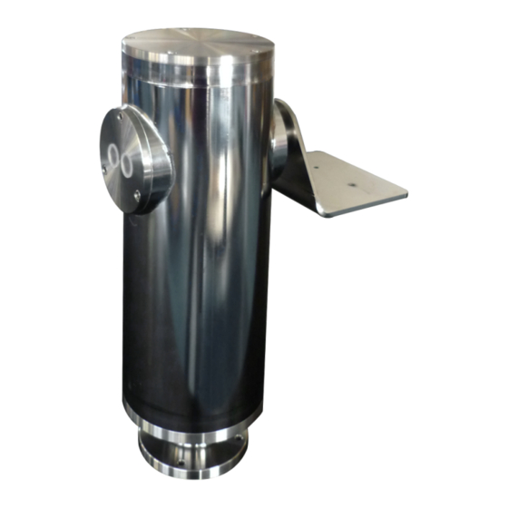
A reliable Pan & Tilt unit is a key feature in video surveillance systems which need to video a wide or a dynamic location. This is why the VSPT Series Pan & Tilt unit is the best choice, especially for Offshore, Marine, Heavy and Food Industry and for every situation where corrosive agents may rapidly damage standard aluminum-steel units. - Page 4 BOTTOM PLATE The unit can be mounted on its appropriate SSBK250 bracket using four M8x1,25 holes arranged on Ø101,6 mm and placed on the bottom plate of the unit. Otherwise, arrange consequently the plane where the unit is meant to be mounted and make sure that it is solid and it can adequately support the weight of the unit and of the camera housing (including the camera and lens).
-
Page 5: Electrical Connections
Electrical Connections Perform electrical connections according to the following connector scheme: M1 P&T MAIN CONNECTOR PAN RIGHT PAN LEFT TILT UP TILT DOWN 0V POT +V POT POT. REF. PAN POT. REF. TILT NON CONNECTED Incorrect Power Supply Voltage may damage the unit. Electrical installation practices Always use color-coded or numbered conductors for wiring and identification ease at a later date. -
Page 6: Default Position
Default Position The unit is in its default position when viewed from front: • the camera housing is placed on the left, with the front window toward the user; • the cable glands are placed on the right. Setting Pan and Tilt limits The Pan and Tilt unit features a manual adjustable setting of both pan and tilt movement, being provided with two adjustable end stop switches for each motion. -
Page 7: Dimensions 07
DIMENSIONS SIDE VIEW FRONTAL VIEW BOTTOM VIEW Dimensions in millimetres – Design and product specifications subject to change without notice TECNOVIDEO S.n.c. Via San L. Murialdo, 8 36030 Villaverla (VI) ITALY Tel. +39.0445.350444 Fax +39.0445.357259 e-mail: info@tecnovideocctv.com – www.tecnovideocctv.com...