
Related Manuals for Hussmann CHINO TY3


Summary of Contents for Hussmann CHINO TY3
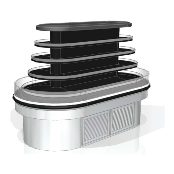
- Page 1 /CHINO Installation TY3, TY4 (ENTYCE) & Operation Manual REV. 0917 ISLAND CASE SELF-CONTAINED...
-
Page 2: Table Of Contents
Table of Contents General Informa• on Cut and Plan Views Spec Sheet Installa• on Close-off Removal Li• ing Instruc• ons Electrical Electrical Wiring Diagram Index Wiring Daigrams Parameter Programmed Report Controller Informa• on and Manual Maintenance Service Tips User Informa• on... - Page 3 1. Do Not Push, Pull, Adjust, or Manipulate the Entyce case by any glass component . • Doing so will result in severe damage to such components • Glass or Acrylic Breakage may result in serious injury • See lifting and transport instructions for proper moving technique ref. pg 7. 2.
- Page 4 This imforma• on is on a platelocated on itself. • REPLACE FILTER EVERY 6 MONTHS, or as needed. A dirty/clogged air www.hussmann.com (909) 590-4910 (800) 395-9229 fi lter restricts the airfl ow. this will result in warmer temperatures in the case, and premature compressor failure.
-
Page 5: General Informa• On
Shortages: Check your shipment for any possible shortages of material. If a shortage should exist and is found to be the responsibility of Hussmann Chino, no• fy Hussmann Chino. If such a shortage involves the carrier, no• fy the carrier immediately, and request an inspec• on. Hussmann Chino will acknowledge shortages within ten days from receipt of equipment. -
Page 6: Cut And Plan Views
Cut and Plan Views... - Page 7 TY3-6 TY3-6X E - Flat End Merchandiser 6' wide Merchandiser (case length) (572) drains centered to straight side (524) (203) Drain 1/2 (114) (1461) (619) (305) (234) Elec (114) (234) (397) Refrig (686) (1854) (1819) 1/2 (114) (397) (114) (762) (556) Drain (889)
-
Page 8: Spec Sheet
Spec Sheet... -
Page 13: Installa• On
Installa• on Store Conditions Do Not Install the Vented Panels of the self-contained model against a wall or • Case is designed to operate at temperatures at either 75°F at at 55% relative humidity or 80°F at 55% relative other storage fi xture. humidity. - Page 14 Figure1 Figure2 Clearances Minimum Clearances for Self-Contained cases are to be followed as instructed for proper placement inside store locations. - Intake and exhaust clearances are to be a minimum of 8’ when placed next to a solid wall. - Height clearance measured from fl oor follows as a minimum of 10’ vertically. - Minimum of 36”...
-
Page 15: Close-Off Removal
Close-off Removal Step 1 Slide bottom of close-off in upward motion to remove from tabs. Step 2 Pull Close-off in outward then downward motion to completely remove side panel close-off Step 3 Once side panel close-off has been removed from case four screws will be visible which fasten the round close-off to the case. -
Page 16: Li• Ing Instruc• Ons
Li• ing Instruc• ons Entyce Lifting and Transport Instructions Lift Zone Jack Points J-Bar Zone 34.42 Dollies under each 72.68 Base Leg 1. The Entyce can be lifted by a forklift only at the speci ed location in the diagram WARNING Improper placement of forks may damage drainage piping. - Page 17 8. If using J-Bars, use the speci ed jacking points to raise the case • Raise one side of the case rst. • Use as many J-Bars as possible to lift from the base channels • A minimum of 2 J-Bars is required •...
- Page 18 Do not Jack or lift at any point J-Bar lift points 8. If using J-Bars, use the speci ed jacking points to raise the case • Raise one side of the case rst. • Use as many J-Bars as possible to lift from the base channels •...
-
Page 19: Electrical
Electrical Field Wiring and Serial Plate Amperage Field Wiring must be sized for component amperes printed on the serial plate. Actual ampere draw may be less than specifi ed. Field wiring from the refrigeration control panel to the merchandisers is required for refrigeration thermostats. - Page 20 REVISION HISTORY CIRCUIT #1 DATE REVISION DESCRIPTION REV BY CHKD BY APPR BY LOADING A ECN-CAP-0008239 2017/09/05 RELEASED TO PRODUCTION 208V 240V 18. 4 21. 3 LIGHT CIRCUIT 16. 4 18.9 . 4 3A 46. 6 W @ 120V COIL OUT DISCHARGE AIR NOTE: WIRES AT SENSOR AKS-12...
- Page 21 REVISION HISTORY CIRCUIT #1 DATE REVISION DESCRIPTION REV BY CHKD BY APPR BY A ECN-CAP-0008239 2017/09/06 RELEASED TO PRODUCTION LOADING 208 V 240V LIGHT CIRCUIT . 3 0A 33W @ 120V 16. 0 18. 4 14. 4 16. 6 DISCHARGE AIR COIL OUT NOTE: WIRES AT SENSOR AKS-12...
- Page 22 REVISION HISTORY CIRCUIT #1 DATE REVISION DESCRIPTION REV BY CHKD BY APPR BY A ECN-CAP-0008239 2017/09/06 RELEASED TO PRODUCTION LOADING 208 V 240V 18. 4 21.2 15. 9 18. 3 DISCHARGE AIR COIL OUT NOTE: WIRES AT SENSOR AKS-11 SENSOR AKS-12 CONTROL INPUTS/OUTPUTS 14GA MAX...
- Page 23 REVISION HISTORY CIRCUIT #1 DATE REVISION DESCRIPTION REV BY CHKD BY APPR BY A ECN-CAP-0008239 2017/09/06 RELEASED TO PRODUCTION LOADING 240V 19. 3 19. 3 DISCHARGE AIR COIL OUT NOTE: WIRES AT SENSOR AKS-11 SENSOR AKS-12 CONTROL INPUTS/OUTPUTS 14GA MAX DANFOSS®...
- Page 24 REVISION HISTORY DATE REVISION DESCRIPTION REV BY CHKD BY APPR BY CIRCUIT #1 LIGHT CIRCUIT A ECN-CAP-0008239 2017/09/06 RELEASED TO PRODUCTION LOADING . 1 6A 37W @ 240V 240V 20. 5 20. 5 DISCHARGE AIR COIL OUT NOTE: WIRES AT SENSOR AKS-11 SENSOR AKS-12 CONTROL...
- Page 25 REVISION HISTORY CIRCUIT #1 LIGHT CIRCUIT DATE REVISION DESCRIPTION REV BY CHKD BY APPR BY . 3 5A 38W @ 120V A ECN-CAP-0008239 2017/09/08 RELEASED TO PRODUCTION LOADING 208 V 240V 20. 2 22. 9 17. 6 20.3 COIL OUT DISCHARGE AIR NOTE: WIRES AT SENSOR AKS-12...
- Page 26 REVISION HISTORY CIRCUIT #1 LIGHT CIRCUIT DATE REVISION DESCRIPTION REV BY CHKD BY APPR BY . 6 9A 74W @ 120V A ECN-CAP-0008239 2017/09/08 RELEASED TO PRODUCTION LOADING 208 V 240V 22. 6 26.1 19. 3 22.3 DISCHARGE AIR COIL OUT NOTE: WIRES AT SENSOR AKS-11 SENSOR AKS-12...
- Page 27 REVISION HISTORY CIRCUIT #1 DATE REVISION DESCRIPTION REV BY CHKD BY APPR BY LIGHT CIRCUIT A ECN-CAP-0008239 2017/09/08 RELEASED TO PRODUCTION LOADING 0. 8 4A 90W @ 120V 208V 240V 26. 5 30. 6 23. 8 26. 3 COIL OUT DISCHARGE AIR NOTE: WIRES AT SENSOR AKS-12...
- Page 28 REVISION HISTORY CIRCUIT #1 DATE REVISION DESCRIPTION REV BY CHKD BY APPR BY A ECN-CAP-0008239 2017/09/08 RELEASED TO PRODUCTION LOADING 208 V 240V LIGHT CIRCUIT . 4 2A 45W @ 120V 19. 9 23. 0 17. 6 20. 3 COIL OUT DISCHARGE AIR NOTE: WIRES AT SENSOR AKS-11...
- Page 29 REVISION HISTORY CIRCUIT #1 DATE REVISION DESCRIPTION REV BY CHKD BY APPR BY LOADING A ECN-CAP-0008239 2017/09/08 RELEASED TO PRODUCTION 208 V 240V LIGHT CIRCUIT . 4 2A 45W @ 120V 23. 1 26. 7 20. 9 24. 1 DISCHARGE AIR COIL OUT NOTE: WIRES AT SENSOR AKS-11...
- Page 30 REVISION HISTORY DATE REVISION DESCRIPTION REV BY CHKD BY APPR BY CIRCUIT #1 A ECN-CAP-0008239 2017/09/08 RELEASED TO PRODUCTION LIGHT CIRCUIT LOADING . 6 3A 68W @ 120V 208V 240V 25. 1 29. 0 21. 8 25. 1 DISCHARGE AIR COIL OUT NOTE: WIRES AT SENSOR AKS-11...
- Page 31 REVISION HISTORY DATE REVISION DESCRIPTION REV BY CHKD BY APPR BY CIRCUIT #1 A ECN-CAP-0008239 2017/09/08 RELEASED TO PRODUCTION LOADING LIGHT CIRCUIT . 9 0A 97W @ 120V 208V 240V 30. 8 35. 6 26. 4 30. 5 COIL OUT DISCHARGE AIR NOTE: WIRES AT SENSOR AKS-12...
- Page 32 REVISION HISTORY CIRCUIT #1 DATE REVISION DESCRIPTION REV BY CHKD BY APPR BY LOADING A ECN-CAP-0009096 2017/08/10 RELEASED TO PRODUCTION b ECN-CAP-0008241 2017/08/21 ADDED PILOT LIGHT 120V 3. 2 LIGHT CIRCUIT 0. 8 6A 93. 2 W @ 120V COIL OUT DISCHARGE AIR NOTE: WIRES AT SENSOR AKS-11...
- Page 33 REVISION HISTORY CIRCUIT #1 DATE REVISION DESCRIPTION REV BY CHKD BY APPR BY LOADING A ECN-CAP-0008241 2017/08/21 RELEASED TO PRODUCTION 120V LIGHT CIRCUIT 3. 2 0. 7 4A 80. 4 W @ 120V COIL OUT DISCHARGE AIR NOTE: WIRES AT SENSOR AKS-12 SENSOR AKS-11 CONTROL...
- Page 34 REVISION HISTORY CIRCUIT #1 DATE REVISION DESCRIPTION REV BY CHKD BY APPR BY A ECN-CAP-0008241 2017/08/22 RELEASED TO PRODUCTION LOADING LIGHT CIRCUIT 208 V 240V . 4 2A 45W @ 120V 17. 5 20. 3 15. 7 18. 3 GFCI DUPLEX CIRCUIT #2 125-01-3178 LOADING...
- Page 35 REVISION HISTORY CIRCUIT #1 DATE REVISION DESCRIPTION REV BY CHKD BY APPR BY A ECN-CAP-0008241 2017/08/22 RELEASED TO PRODUCTION LOADING LIGHT CIRCUIT . 7 6A 82W @ 120V 208V 240V 20. 8 24. 0 18. 1 20. 9 COIL OUT DISCHARGE AIR NOTE: WIRES AT SENSOR AKS-12...
- Page 36 REVISION HISTORY CIRCUIT #1 DATE REVISION DESCRIPTION REV BY CHKD BY APPR BY A ECN-CAP-0008241 2017/08/22 RELEASED TO PRODUCTION LOADING 208 V 240V LIGHT CIRCUIT 21. 3 24. 6 . 4 1A 44W @ 120V 19. 1 22. 0 COIL OUT DISCHARGE AIR NOTE: WIRES AT SENSOR AKS-12...
- Page 37 REVISION HISTORY CIRCUIT #1 DATE REVISION DESCRIPTION REV BY CHKD BY APPR BY LIGHT CIRCUIT A ECN-CAP-0008241 2017/08/22 RELEASED TO PRODUCTION . 7 9A 85W @ 120V LOADING 208 V 240V 18. 6 21. 4 15. 8 18. 3 DISCHARGE AIR COIL OUT NOTE: WIRES AT SENSOR AKS-11...
- Page 38 REVISION HISTORY LIGHT CIRCUIT CIRCUIT #1 DATE REVISION DESCRIPTION REV BY CHKD BY APPR BY 0. 3 9A 93W @ 240V A ECN-CAP-0008241 2017/08/22 RELEASED TO PRODUCTION LOADING 240V 27. 6 27. 6 COIL OUT DISCHARGE AIR NOTE: WIRES AT SENSOR AKS-12 SENSOR AKS-11 CONTROL...
- Page 39 REVISION HISTORY CIRCUIT #1 LIGHT CIRCUIT DATE REVISION DESCRIPTION REV BY CHKD BY APPR BY 1.18A 127W @ 120V A ECN-CAP-0008241 2017/08/23 RELEASED TO PRODUCTION LOADING 208 V 240V 31.4 36.2 27.6 31.8 DISCHARGE AIR COIL OUT NOTE: WIRES AT SENSOR AKS-12 SENSOR AKS-11 CONTROL...
-
Page 40: Parameter Programmed Report
Parameter Programmed Report ( ))%) )% ( ))%) )* "#$#%$ & "#$#%$ "# " " "# " &'() + , -+ /" 1 * 2 * ') ' 3 !. * 4 2 /"5 5+/"2 5+/ ! ) * *) ) &* 1 "... - Page 41 Parameter Programmed Report !" &% & & & & & & & & 23 . - 7- 7 ) 75) $ ! 8 6 + * #$ 23 . < - 8 8 6 8 8 6 & ##...
- Page 42 User Guide Controller for temperature control AK-CC 210 ADAP-KOOL® Refrigeration control systems...
- Page 43 Contents Introduction ....................... 2 Operation ......................18 Operation ......................3 Menu survey .....................20 Applications ....................... 6 Ordering ......................22 Survey of functions ..................8 Connections .....................23 Data ........................24 Introduction Application • The controller is used for temperature control refrigeration appliances in supermarkets •...
-
Page 44: Operation
Operation Sensors Up to two thermostat sensors can be connected to the controller. The relevant application determines how. A sensor in the air before the evaporator: This connection is primarily used when control is based on area. A sensor in the air after the evaporator: This connection is primarily used when refrigeration is controlled and there is a risk of a too low temperature near the products. - Page 45 Digital inputs There are two digital inputs both of which can be used for the following functions: - Case cleaning - Door contact function with alarm - Starting a defrost - Coordinated defrost - Change-over between two temperature reference - Retransmission of a contact’s position via data communication Case cleaning function This function makes it easy to steer the refrigeration appliance through a cleaning phase.
- Page 46 Coordinated defrost There are two ways in which coordinated defrost can be arranged. Either with wire connections between the controllers or via data communication Max. 15 Wire connections One of the controllers is de ned to be the controlling unit and a battery module may be tted in it so that the clock is ensured backup.
- Page 47 Applications S3 and S4 are temperature sensors. The application will deter- Here is a survey of the controller’s eld of application. mine whether either one or the other or both sensors are to be used. S3 is placed in the air ow before the evaporator. S4 after A setting will de ne the relay outputs so that the controller’s the evaporator.
- Page 48 Refrigeration control with two compressors This group of applications can be used if the controller is to cut two compressors in and out. The functions can be compared with wiring diagrams 1 to 3, but instead of controlling fans the relay is here used for compressor The two compressors must be of the same size.
- Page 49 Survey of functions Function Para- Parameter by operation via data meter communication Normal display Normally the temperature value from one of the two thermostat sensors S3 or S4 or a Display air (u56) mixture of the two measurements is displayed. In o17 the ratio is determined.
- Page 50 Activation of reference displacement Th. o set When the function is changed to ON the thermostat reference will be displaced by the value in r40. Activation can also take place via input DI1 or DI2 (de ned in o02 or o37).
- Page 51 Time delay for couplings of two compressors Step delay Settings indicate the time that has to elapse from the rst relay cuts in and until the next relay has to cut in. Reversed relay function for D01 Cmp relay NC 0: Normal function where the relay cuts in when refrigeration is demanded 1: Reversed function where the relay cuts out when refrigeration is demanded (this wiring produces the result that there will be refrigeration if the supply voltage to the...
- Page 52 Drip-o time DripO time Here you set the time that is to elapse from a defrost and until the compressor is to start again. (The time when water drips o the evaporator). Delay of fan start after defrost FanStartDel Here you set the time that is to elapse from compressor start after a defrost and until the fan may start again.
- Page 53 Fan stop temperature FanStopTemp. The function stops the fans in an error situation, so that they will not provide power to the appliance. If the defrost sensor registers a higher temperature than the one set here, the fans will be stopped. There will be re-start at 2 K below the setting. The function is not active during a defrost or start-up after a defrost.
- Page 54 Digital input signal - DI1 DI 1 Con g. The controller has a digital input 1 which can be used for one of the following func- De nition takes place with the nu- tions: merical value shown to the left. O : The input is not used 1) Status display of a contact function (0 = o )
- Page 55 Digital input signal - D2 DI2 con g. The controller has a digital input 2 which can be used for one of the following func- tions: O : The input is not used. 1) Status display of a contact function 2) Door function.
- Page 56 Copy from the programming key This function downloads a set of settings earlier saved in the controller. Select the relevant number. All settings except for Application (o61) and Address (o03) will be copied. When copy- ing has started the display returns to o66. After two seconds you can move back into the menu again and check whether the copying was satisfactory.
- Page 57 Fault message Alarms In an error situation the LED’s on the front will ash and the alarm relay will be acti- vated. If you push the top button in this situation you can see the alarm report in the display. If there are more keep on pushing to see them. There are two kinds of error reports - it can either be an alarm occurring during the daily operation, or there may be a defect in the installation.
- Page 58 Operating status (Measurement) The controller goes through some regulating situations where it is just waiting for EKC State: the next point of the regulation. To make these “why is nothing happening” situations (Shown in all menu displays) visible, you can see an operating status on the display. Push brie y (1s) the upper but- ton.
-
Page 59: Operation
Operation Set temperature 1. Push the middle button until the temperature value is shown Display 2. Push the upper or the lower button and select the new value The values will be shown with three digits, and with a setting you 3. - Page 60 HACCP The readout of the various values in the HACCP function can take This function will follow the appliance temperature and sound an place with a long push on the middle button. alarm if the set temperature limit is exceeded. The alarm will come The readouts are, as follows: when the time delay has elapsed.
-
Page 61: Menu Survey
Menu survey SW = 2.3x Parameters EL-diagram number (page 6) Min.- Max.- Factory Actual Function Codes value value setting setting Normal operation Temperature (set point) -50.0°C 50.0°C 2.0°C Thermostat Di erential 0.1 K 20.0K 2.0 K Max. limitation of setpoint setting -49.0°C 50°C 50.0°C... - Page 62 Input signal on DI1. Function: 0=not used. 1=status on DI1. 2=door function with alarm when open. 3=door alarm when open. 4=defrost start (pulse-signal). 5=ext.main switch. 6=night operation 7=change reference (activate r40). 8=alarm function when closed. 9=alarm function when open. 10=case cleaning (pulse signal). 11=forced cooling at hot gas defrost.
-
Page 63: Ordering
Auxiliary table for settings Case Room (quick-setup) Defrost stop on Defrost stop Defrost stop on Defrost stop time on S5 time on S5 Preset settings (o62) Temperature (SP) 4°C 2°C -24°C 6°C 3°C -22°C Max. temp. setting (r02) 6°C 4°C -22°C 8°C 5°C... -
Page 64: Connections
Connections Relays The general uses are mentioned here. See also page 6 where the di erent applications are shown. DO1: Refrigeration. The relay will cut in when the controller de- mands refrigeration DO2: Defrost. The relay will cut in when defrost is in progress DO3: For either fans or refrigeration 2 Fans: The relay will cut in when the fans have to operate Refrigeration 2: The relay will cut in when refrigeration step 2... -
Page 65: Data
Data Supply voltage 230 V a.c. +10/-15 %. 2.5 VA, 50/60 Hz Pt 1000 or Sensors 3 pcs o PTC 1000 or either NTC-M2020 (5000 ohm / 25°C) Measuring range -60 to +99°C ±1 K below -35°C Controller ±0.5 K between -35 to +25°C Accuracy ±1 K above +25°C ±0.3 K at 0°C... - Page 66 Maintenance Case Cleaning • DO NOT USE A CLEANING OR SANITIZING SOLUTION THAT HAS AN OIL BASE (these will dissolve the butyl To insure long life, proper sanitation and minimum sealants) or an AMMONIA BASE (this will corrode the maintenance costs, the refrigerator should be thoroughly copper components of the case) cleaned frequently.
- Page 67 Service Tips WARNING ALWAYS DISCONNECT THE ELECTRICAL POWER AT THE MAIN DISCONNECT WHEN SERVICING OR REPLACING ANY ELECTRICAL COMPONENT OF THIS REFRIGERATOR. THIS INCLUDES, BUT IS NOT LIMITED TO SUCH ITEMS AS FANS AND THERMOSTATS. Fan Blade Replacement 3) Install honeycomb by inserting the notched side up against the defl...
- Page 68 Hussmann cases were not or detergent based cleaners. Sanitizing solutions will not designed to “heat up” or “cool down” product - but rather to harm the interior bottom, however, these solutions should maintain an item’s proper temperature for maximum shelf...
- Page 69 Additional copies of this publication may be obtained by contacting: They can be found on a small metal plate on the unit. Hussmann® Chino Please note them below for future reference. 13770 Ramona Avenue • Chino, California 91710...
Need help?
Do you have a question about the CHINO TY3 and is the answer not in the manual?
Questions and answers