Table of Contents
Advertisement
Quick Links
International HQ
Jerusalem, Israel
Tel: + 972 2 535 9666
minicom@minicom.com
SmartRack
Quick Installation Guide
w w w . m i n i c o m . c o m
North American HQ
Linden, NJ, USA
Tel: + 1 908 486 2100
info.usa@minicom.com
Technical support - support@minicom.com
European HQ
Dübendorf, Switzerland
Tel: + 41 44 823 8000
info.europe@minicom.com
5UM20180 V1.1 11/08
Advertisement
Table of Contents

Related Manuals for Minicom SmartRack

Summary of Contents for Minicom SmartRack
- Page 1 North American HQ European HQ Jerusalem, Israel Linden, NJ, USA Dübendorf, Switzerland Tel: + 972 2 535 9666 Tel: + 1 908 486 2100 Tel: + 41 44 823 8000 minicom@minicom.com info.usa@minicom.com info.europe@minicom.com Technical support - support@minicom.com 5UM20180 V1.1 11/08...
-
Page 2: System Components
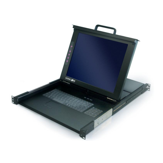
The SmartRack from Minicom is a slim, rack mountable console drawer. The SmartRack can be used as a stand alone unit or connected to a 16 port KVM Switch or 16 port KVM IP switch. Occupying just 1U of rack space, it’s the neat, space-saving way to control your data rack. -
Page 3: Avoiding General Rack Mounting Problems
QUICK INSTALLATION GUIDE Short bracket x 2 Bracket attachment x 2 Note! The short bracket and bracket attachment for a rack depth of 504~ 614 mm and without a KVM switch connected to the drawer. Flat screws x 6 (for rail mount to console body) Screws x 6 Bracket A with thumbscrew x 2 Screws x4... -
Page 4: Connecting To A Rack
Note! For increased rack depth of 905 ~ 990mm, first change the bracket, see section 6 on page 5. Note! The illustrations below show the connections to one side of the SmartRack. The connections are the same for the other side. - Page 5 Figure 5 Tightening the 7 screws 6. Repeat the steps above to connect the other rail to the other side of the rack. 7. Slide the SmartRack console between the rails as shown below. Figure 6 Sliding the SmartRack between the rails 8.
- Page 6 SMARTRACK Figure 7 Rail–lock switch 9. Connect three flat screws to the rear of the console on both sides. See figure below. Figure 8 Connecting three flat screws to the rear of the console The console now sits snugly in the rack, see Figure 9.
- Page 7 QUICK INSTALLATION GUIDE Figure 10 Loosening the 7 screws Remove the six (different) screws as shown below. Figure 11 Removing the six screws 2. Take the rear bracket out, see below. Figure 12 Taking the rear bracket out 3. Insert the long bracket into the rail then adjust the bracket to fit your cabinet. Tighten at least 2~3 screws along the length you need.
- Page 8 Figure 14 Connecting the bracket A to the sides of the Switch 2. Slide the Switch 116 into the rail and into the back of the SmartRack console until you hear a click. See the figure below.
-
Page 9: Pre-Installation Guidelines
Place cables away from fluorescent lights, air conditioners, and machines that are likely to generate electrical noise • Ensure that the maximum distance between each computer and the SmartRack Switch, does not exceed 10m/33ft for RICCs and 30m/100ft for ROCs 9. The SmartRack Switch system configuration You connect servers to the 116 and 116IP switches via ROCs or RICCs. -
Page 10: Connector Table
CAT5 cables Up to 10M / 33ft User over IP Internet / VPN / LAN To servers ROC/RICCs to servers Figure 18 SmartRack 116IP Switch system configuration 10. The 116 and 116IP switches MINICOM SMARTRACK 116 SWITCH Download Power connector... - Page 11 QUICK INSTALLATION GUIDE SERIAL MINICOM SMARTRACK 116IP SW ITCH FLASH Flash LAN (Ethernet) (download) connector Power Server ports connector connector Figure 20 116IP Switch ports Connector table Connector Function Serial This port is for future Serial functionality Flash To update firmware of the analogue part of the 116 IP Switch system - OSD, Switch, RICCs and ROCs.
- Page 12 SMARTRACK 11. Connecting ROC or RICC to servers Each computer/ server is directly connected to the SmartRack switch via the appropriate ROC or RICC using CAT5 cable in a star configuration. The system can contain a mixture of ROCs and RICCs. No external power is needed at the remote ROC/RICCs.
- Page 13 QUICK INSTALLATION GUIDE NetServer tc2100 To Keyboard port To Mouse port RICC To Video port SCSI CAT5 cable to Switch PCI 33Mx32b Computer port PCI 33Mx32b PCI 33Mx32b PCI 33Mx32b Figure 23 RICC PS/2 connections Connecting a ROC/RICC USB The ROC/RICC USB supports Windows 98 SE and later, MAC, SUN, SGI and all modern Linux distributions.
-
Page 14: Connecting The Cat5 Cables
3. Follow the above 2 steps for each computer. 13. Connecting to the network For the SmartRack 116IP Switch, connect the network cable to the LAN port. This must be done before powering on the SmartRack 116IP Switch. 14. Connecting the power supply 1. - Page 15 Italy Kiel Vincennes Rome Tel: + 49 431 668 7933 Tel: + 33 1 49 57 00 00 Tel: + 39 06 8209 7902 info.minicom-germany@minicom.com info.france@minicom.com info.italy@minicom.com England China Asia Pacific / S. Korea Beijing Tel: + 44 121 288 0608...
Need help?
Do you have a question about the SmartRack and is the answer not in the manual?
Questions and answers