
Subscribe to Our Youtube Channel
Related Manuals for IBASE Technology IP417


Summary of Contents for IBASE Technology IP417
- Page 1 IP417 Mini-ITX COM Express Type 10 (R3.0) Carrier Board User’s Manual Version 1.0 (July 2019)
- Page 2 IBASE Technology, Inc. (hereinafter referred to as “IBASE”). Disclaimer IBASE reserves the right to make changes and improvements to the products described in this document without prior notice.
-
Page 3: Compliance
0.1% by weight (1000 ppm) except for cadmium, limited to 0.01% by weight (100 ppm). • Lead (Pb) • Mercury (Hg) • Cadmium (Cd) • Hexavalent chromium (Cr6+) • Polybrominated biphenyls (PBB) • Polybrominated diphenyl ether (PBDE) IP417 User’s Manual... -
Page 4: Important Safety Information
Danger of explosion if the internal lithium-ion battery is replaced by an incorrect type. Replace only with the same or equivalent type recommended by the manufacturer. Dispose of used batteries according to the manufacturer’s instructions or recycle them at a local recycling facility or battery collection point. IP417 User’s Manual... -
Page 5: Warranty Policy
Software in use (such as OS and application software, including the version numbers) If repair service is required, you can download the RMA form at http://www.ibase.com.tw/english/Supports/RMAService/. Fill out the form and contact your distributor or sales representative. IP417 User’s Manual... -
Page 6: Table Of Contents
Chapter 2 Hardware Configuration .......... 7 Setting the Jumpers ................8 2.2.1 How to Set Jumpers ............... 8 Connector Locations on IP417 ............. 9 Jumpers Quick Reference ..............10 2.3.1 BIOS Boot Selection (JP1, JP9) .......... 10 2.3.2 COM1 RS-232 Power Selection (JP2) ......... 11 2.3.3... - Page 7 DC-In 12V Power Connector (J14) ........17 2.4.7 COM1 & COM2 Ports (CN2) ..........17 2.4.8 LVDS Connector (CN10) ............. 18 2.4.9 eDP Connector (CN15) ............19 2.4.10 Fan Power Connector (CPU_FAN1) ........19 Appendix ..................21 Onboard Connector Types ..............22 IP417 User’s Manual...
- Page 8 This page is intentionally left blank. IP417 User’s Manual viii...
-
Page 9: Chapter 1 General Information
Chapter 1 General Information The information provided in this chapter includes: • Features • Specifications • Board Overview • Board Dimensions... -
Page 10: Introduction
Introduction IP417 is a carrier board for mini-ITX COM Express Type 10 (R3.0) CPU module. It features expansion slots for a PCIe and two mini-PCIe slots and I/O interface for a DP display, two RJ45, eight USB 3.0 and two USB 2.0 ports. It measures 170mm x 170mm. -
Page 11: Specifications
• COM1 & COM2: RS-232 (full-function) (edge I/O connector) Serial • COM3 & COM4: RS-232 (TX and RX only) (from the COMe module, via an on-board box-headers) Derived from COMe module. Serial ATA 2 x SATA 3.0 IP417 User’s Manual... - Page 12 2 x Mini-PCIe slot Environment • Operating: -40 ~ 85°C (-40 ~ -185°F) Temperature Storage: -40 ~ 90 °C (-40 ~ 194°F) • Relative 10 ~ 90 % (non-condensing) Humidity All specifications are subject to change without prior notice. IP417 User’s Manual...
-
Page 13: Overview
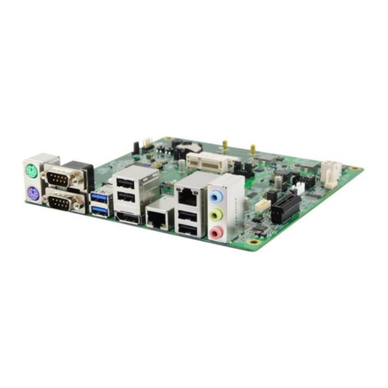
USB 2.0 Ports PS/2 Keyboard Port GbE LAN Ports COM1 RS-232 Port Microphone Input COM2 RS-232 Ports Audio Line-Out USB 3.0 Port Audio Line-In DisplayPort *The photos above are for reference only. Some minor components may differ. IP417 User’s Manual... -
Page 14: Dimensions
Dimensions IP417 User’s Manual... -
Page 15: Chapter 2 Hardware Configuration
Chapter 2 Hardware Configuration This section provides information on jumper settings and connectors on the board in order to set up a workable system. • Jumper and connector locations • Jumper settings and information of connectors... -
Page 16: Setting The Jumpers
Open When two pins of a jumper are encased in a jumper cap, this jumper is closed, i.e. turned On. When a jumper cap is removed from two jumper pins, this jumper is open, i.e. turned Off. IP417 User’s Manual... -
Page 17: Connector Locations On Ip417
Hardware Configuration Connector Locations on IP417 Board diagram of IP417 IP417 User’s Manual... -
Page 18: Jumpers Quick Reference
LVDS Backlight Power Selection eDP Backlight Power Selection JP10 AT / ATX Mode Selection JP11 2.3.1 BIOS Boot Selection (JP1, JP9) Pin closed SPI_CS0# SPI_CS1# SPI0/FWH Module Module SPI0 (default) Module Module Carrier FWH Carrier Module SPI0/SPI1 Module Carrier SPI0/SPI1 IP417 User’s Manual... -
Page 19: Com1 Rs-232 Power Selection (Jp2)
Hardware Configuration 2.3.2 COM1 RS-232 Power Selection (JP2) Function Pin closed Illustration Normal (default) 2.3.3 COM2 RS-232 Powr Selection (JP3) Function Pin closed Illustration Normal (default) IP417 User’s Manual... -
Page 20: Ps/2 Mouse/Keyboard Power Selection (Jp4)
5VSB (default) 2.3.5 eDP / LVDS Function Setting (JP5) Function Pin closed Illustration (default) LVDS 2.3.6 LVDS Panel Power (JP6) Function Pin closed Illustration 3.3V (default) 2.3.7 eDP Panel Power (JP7) Function Pin closed Illustration 3.3V (default) IP417 User’s Manual... -
Page 21: Lvds Backlight Power Selection (Jp8)
LVDS Backlight Power Selection (JP8) Function Pin closed Illustration 3.3V (default) 2.3.9 eDP Backlight Power Selection (JP10) Function Pin closed Illustration (default) 2.3.10 AT / ATX Mode Selection (JP11) Function Pin closed Illustration AT Mode ATX Mode (default) IP417 User’s Manual... -
Page 22: Connectors Quick Reference
GbE LAN Port CN6, CN8 USB 2.0 SATA 3 Connector CN9, CN11 LVDS Connector CN10 eDP Connector CN15 COMe Connector RECS1 PCIe (x1) Slot PCIEX1 Fan Power Connector CPU_FAN1 Power Button Reset Button Factory Use Only J3, J10 IP417 User’s Manual... -
Page 23: Sata Hdd Power Connector (J1, J2)
Signal Name Ground Ground +12V 2.4.2 LVDS Panel Inverter Power Connector (J6) Signal Name Signal Name +12V Backlight Enable Ground 2.4.3 COM3 & COM4 Ports (J13, J8) Signal Name Signal Name RXD, Receive data TXD, Transmit data Ground IP417 User’s Manual... -
Page 24: Gpio Connector (J17)
When pressed again, it will power off the system. • Hard Disk Drive LED Connector (Pins 3 and 4) This connector connects to the hard drive activity LED on control panel. This LED will flash when the HDD is being accessed. IP417 User’s Manual... -
Page 25: Dc-In 12V Power Connector (J14)
COM1 & COM2 Ports (CN2) COM1: COM2: Signal Name Signal Name DCD, Data carrier detect DSR, Data set ready RXD, Receive data RTS, Request to send TXD, Transmit data CTS, Clear to send DTR, Data terminal ready RI, Ring indicator Ground IP417 User’s Manual... -
Page 26: Lvds Connector (Cn10)
2.4.8 LVDS Connector (CN10) The LVDS connector supports single-channel 18-bit or 24-bit displays. Signal Name Signal Name TX0P TX0N Ground Ground TX1P TX1N Ground Ground TX2P TX2N Ground Ground CLKP CLKN Ground Ground TX3P TX3N Power Power IP417 User’s Manual... -
Page 27: Edp Connector (Cn15)
Backlight Power EDP Power Backlight Power Ground AUXN AUXP Backlight CTRL Ground Backlight Enable TX0P Ground TX0N Ground Ground Ground TX1P Ground TX1N Ground Ground 2.4.10 Fan Power Connector (CPU_FAN1) Signal Name Signal Name Ground Rotation detection +12V IP417 User’s Manual... - Page 28 This page is intentionally left blank. IP417 User’s Manual...
-
Page 29: Appendix
Appendix This section provides the mapping addresses of peripheral devices, the sample code of watchdog timer configuration, and types of on-board connectors. -
Page 30: Onboard Connector Types
Panel Inverter JST B4B-PH-K-S Power PHR-4 Connector COM3 & COM4 J13 (COM3), Hao Guo Xing Ye RX/TX Port J18 (COM4) DF11-10S-PA66H DF11-10DS-2C System E-Call Dupont Function 0126-01-203-080 2.54mm-pitch Connector (Female) Fan Power E-Call Molex CPU_FAN1 Conector 0110-02-111-030 22-01-2031 IP417 User’s Manual...
Need help?
Do you have a question about the IP417 and is the answer not in the manual?
Questions and answers