Table of Contents
Advertisement
Quick Links
Attention
Beijing Aeonmed Co., Ltd. (hereinafter referred to as "our company") holds the copyrights to
this non-public published manual, and reserves the rights to keep it as a secure document.
Refer to this manual when operating, maintaining and repairing products only. Only our
company may provide permission for the use of or copies of this document to others.
Proprietary materials protected by the copyright law are included in this manual. No section of
it may be duplicated, copied, or translated into other languages without prior written approval
from our company who reserves the copyright.
Everything written within this manual is considered to be correct, but it is not a substitute for
the exercise of professional judgment. Our company is not legally responsible for any mistakes
printed within and/or any damages caused by incorrect connection and operation of equipment.
Our company does not supply privileges endowed by the patent law to any other parties. Our
company is not legally responsible for the results caused by patent law breaking or any rights
of the third party violating.
Any user must read this article before using the products of our company. This article exposes
the operating steps that must be read carefully. Improper use might endanger equipment or
persons. The company will not undertake the responsibility for the safety, reliability and
performance if equipment is used improperly. The company will not offer complimentary
service for misused equipment.
Our company has the right to revise any content in this manual without notice; and has no
obligation to update either hardware or software of the equipment described herein to the user
or owner.
i
Advertisement
Table of Contents

Related Manuals for Aeonmed vg70


Summary of Contents for Aeonmed vg70
- Page 1 Attention Beijing Aeonmed Co., Ltd. (hereinafter referred to as "our company") holds the copyrights to this non-public published manual, and reserves the rights to keep it as a secure document. Refer to this manual when operating, maintaining and repairing products only. Only our company may provide permission for the use of or copies of this document to others.
- Page 2 Warning for use Welcome to use our products! In order to use this product correctly and effectively, please read these operating instructions carefully and completely before using the product for the first time. When using the product, always proceed in accordance with the information provided in these operating instructions on the basis of fully understanding the information in this manual.
- Page 3 Manufacturer(holder): Beijing Aeonmed Co., Ltd. Room 405 , Basement 1 to 4th Floor of 901 Unit, Manufacturer(holder) address: Building 9, No.26 Outer Ring West Road, Fengtai District, Beijing 100070, China Facilit : Bei in Aeonmed Co., Ltd.
-
Page 5: Table Of Contents
Abbreviations and Definitions ..................1-8 Frequently Used functions .................... 1-10 1.10 Symbols ......................... 1-10 1.11 VG70 Ventilator Quick Start Guide ................1-12 System Overview ......................2-1 Ventilator Components ....................2-1 User Interface Components .................... 2-2 2.2.1 GUI Screen Front Panel ................... 2-2 2.2.2... - Page 6 Connect Gas Source ......................4-1 Connect Accessories ......................4-2 4.3.1 Connect Patient circuit .................... 4-2 4.3.2 Connect Humidifier (optional) ................4-3 4.3.3 Connect Patient Circuit Positioning Arm (optional) ..........4-3 4.3.4 Connect User Interface Screen................4-4 4.3.5 Connect Cylinder Kit (optional) ................4-4 Pre-use Test ........................
- Page 7 BiLevel Ventilation (BIVENT) ................. 10-7 10.1.6 Non Invasive/Continuous Positive Airway Pressure ..........10-8 10.1.7 NIV-T ........................10-10 10.1.8 NIV-S/T ........................ 10-10 11 VG70 Ventilator System Specifications ............... 11-1 11.1 System ........................... 11-1 11.1.1 General ........................11-1 11.1.2 Operating Conditions .................... 11-2 11.1.3...
- Page 8 11.7.2 Alarms Miscellaneous ................... 11-7 11.8 Ventilation Modes ......................11-8 11.8.1 Controlled Ventilation ................... 11-8 11.8.2 Supported Ventilation ................... 11-8 11.8.3 Combined Ventilation ................... 11-8 11.9 Trend Function ......................11-9 11.10 Log Function ........................ 11-10 11.11 Shortcut Key Functions ....................11-10 11.12 Communication/Interface ...................
-
Page 9: Introduction
1 Introduction 1 Introduction Review all information in this manual thoroughly before attempting to use the equipment. This equipment must be used under the supervision of a physician. 1.1 Manufacturer’s Responsibility Our company is responsible for the security; reliability and functions of the equipment, only when the following requirements are strictly adhered to: ... -
Page 10: Definitions
1.3 Definitions This manual uses three special indicators to convey information of a specific nature. They include: Indicates a condition that can endanger the patient or the ventilator operator. WARNING: Indicates a condition that can damage the equipment. CAUTION: Indicates points of particular emphasis that make operation of the ventilator more efficient or convenient. - Page 11 1 Introduction WARNING: If a fault is detected in the ventilator so that its life support functions are no longer assured: start ventilation using an independent ventilation device (resuscitation bag) without delay, if necessary with PEEP and/or increased inspiratory O concentration.
-
Page 12: Cautions
WARNING: Adding attachments or other components or sub-assemblies to the ventilator breathing system can change the pressure gradient across the ventilator breathing system and that such changes to the ventilation breathing system can affect the ventilator performance. WARNING: Expiratory module is heated; use caution to avoid burns. WARNING: Use caution when handling flammable or fragile components. - Page 13 1 Introduction CAUTION: Follow your hospital infection control guidelines for handling infectious material. Our company recognizes that cleaning, sterilization, sanitation, and disinfection practices vary widely among health care institutions. It is not possible for our company to specify or require specific practices that will meet all needs, or to be responsible for the effectiveness of cleaning, sterilization, and other practices carried out in the patient care setting.
-
Page 14: Notes
CAUTION: The Network interface connection is for authorized service only. CAUTION: Batteries should be removed if equipment will not be in service for more than 6 months. See Section 8.5 for battery replacement guidance. CAUTION: Do not immerse the oxygen sensor or the connector in any type of liquid. CAUTION: When ventilator is exposed to conditions outside the specified operating environment, allow 24 hours in normal environment before using. -
Page 15: Intended Use
STPD (standard temperature and pressure dry), except when specified with another condition. 1.5 Intended Use The VG70 Ventilator System is intended to provide continuous ventilation treatment to patients and monitoring of patients with respiratory failure or respiratory insufficiency, requiring respiratory support. -
Page 16: Contraindication
1.7 Contraindication WARNING: The Ventilator is not intended for use in areas with risk of explosion. Do not operate the ventilator in the presence of flammable anesthetics. WARNING: The Ventilator is not designed for use in an MRI environment. Do not use the Ventilator near an MRI machine;... - Page 17 1 Introduction PEEPi Intrinsic Positive End-Expiratory Pressure (M) Upper pressure level in PCV mode (S) insp Mean airway pressure. This value is updated at the end of the last respiratory mean cycle, hence, is a continuous average (M) Airway pressure peak value during one ventilatory cycle (M) peak End-inspiratory airway pressure (M) plat...
-
Page 18: Frequently Used Functions
Rinsp Inspiratory resistance (M) Rexp Expiratory resistance (M) Elastic Elastic resistance (M) IP21 Solid particle protection level 2; Liquid ingress protection level 1 1.9 Frequently Used functions (1) Power On / Off Switch (2) Connect patient hoses and gas supply (3) Pre-Use Test (4) Settings (5) Start Ventilation/Standby... - Page 19 1 Introduction EQUIPOTENTIAL connection loudspeaker Lock Manufacturer Unlock Date of production Inspiratory hold Serial Number Nebulization Expiratory hold Intelligent increase of oxygen Manual inspiration Standby Waveform freeze AC power int. Internal Battery USB device Refer to documentation Prompt message Already online Flow trigger Pressure trigger Adult...
-
Page 20: Vg70 Ventilator Quick Start Guide
Do not reuse Disposal of Waste 1.11 VG70 Ventilator Quick Start Guide Review all information in the Operator’s Manual before attempting to use this equipment. 1. Connect Power Supply Connect to AC Power Source, DC Power Source or Utilize Battery 2. - Page 21 1 Introduction 5. Pre-use Test 6. Select New Patient 7. Prepare Patient Circuit 8. Connect CO Module (optional) 9. Connect IRMA Airway Adapter (optional) 1-13...
- Page 22 10. Set Appropriate Ventilation Settings 1-14...
-
Page 23: System Overview
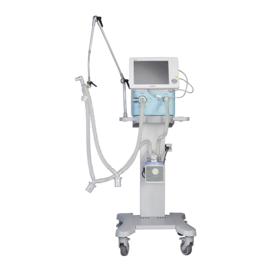
Graphical User Interface (GUI). Optional Components available for the Critical Care Ventilator system are: Cart, Battery Backup Assembly, Patient Circuit Positioning Arm, Patient Circuit Assemblies and CO module, etc. Figure 2-1 VG70 profile Humidifier Patient Circuit Main Control Unit Water Trap Nebulizer Tube... -
Page 24: User Interface Components
Breathing parameters are continuously measured by transducers and controlled by a feedback system in the Breathing Delivery Unit. The ventilator responds to a difference between the actual measured value of a parameter and the preset or calculated value by adjusting gas delivery to achieve the target value. -
Page 25: Gui Screen Side Panel
2 System Overview 2.2.2 GUI Screen Side Panel Figure 2-3 GUI screen side panel 1. Main cable: This cable connects the GUI screen and the main control unit. CAUTION: Do not disconnect this cable when the ventilator is operating. 2. VGA interface: For connection of a VGA display which will display the same information as the GUI screen. -
Page 26: Main Control Unit
2.3 Main Control Unit The main control unit is responsible for control of the ventilator. It has interfaces on the front and rear panels including pneumatic and electronic interfaces. 2.3.1 Front Panel Figure 2-4 Front panel 1. Expiratory module: To remove the Expiratory module: Press the latch (5) on the right part of front cover (i.e. -
Page 27: Rear Panel
2 System Overview CAUTION: Do not block this port. CAUTION: Do not connect inspiratory or expiratory limb circuit to this port. 3. Expiratory port CAUTION: Do not connect inspiratory limb circuit to this port. 4. Water trap cup: Collect condensed water to prevent it from going into expiratory valve. 5. -
Page 28: Cart
Battery Cover Module Connector Nurse Call Connector Air Inlet Low-flow Oxygen Inlet Hyperbaric Oxygen Inlet Cooling Fan DC Power Fuse DC Power Input Port Equipotential Terminal 11 Power Supply Socket 12 Power Supply Switch CAUTION: The Equipotential Terminal is used to connect various parts of the equipment or of a medical equipment system to the same potential. -
Page 29: Co 2 Module
3 CO Module 3 CO Module 3.1 CO Module Intended Use The mainstream CO module is intended to be connected to the Ventilator for display of real time and derived monitoring data of CO The mainstream CO module is intended to be connected to a patient breathing circuit for monitoring of inspired/expired gases during recovery and respiratory care. - Page 30 according to EN1789:2007 (clause 6.4) and requirements for shock and vibration according to EN ISO 80601-2-55 (clause 201.15.3.5.101). Surface temperature (at ambient temp. Max 41° C / 106° F 23° C) Disposable adult/pediatric: Adds less than 6 ml dead space; Pressure drop less than 0.3 cmH O @ 30 LPM.
- Page 31 3 CO Module Accuracy specifications – during all conditions Accuracy ± (0.3 vol% + 4% of reading) NOTE 1: The accuracy specification is valid for the operating temperature and humidity conditions specified, except for interference specified in the table “Interfering gas and vapor effects”...
- Page 32 vol% CO and 50 vol%. Helium, the measured CO concentration will typically be (1-0.06) * 5.0 vol% = 4.7 vol % CO NOTE 3: According to the ISO 80601-2-55 standard. NOTE 4: In addition to the ISO 80601-2-55 standard. CAUTION: The presence of oxygen can cause some interference in the CO measurement.
-
Page 33: System Assembly Instruction
3 CO Module 3.3 System Assembly Instruction 3.3.1 Set-up 1. Plug the IRMA connector into the CO module connector on Ventilator rear panel and switch the power on. 2. Snap the IRMA probe on top of the IRMA airway adapter. It will click into place when properly seated. - Page 34 5. Connect the IRMA/airway adapter 15 mm female connector to the patient’s endotracheal tube. Alternatively, connect a HME (Heat Moisture Exchanger) between the patient’s endotracheal tube and the IRMA probe. Placing a HME in front of the IRMA probe protects the airway adapter from secretions and effects of water vapor and eliminates the need of changing the adapter.
-
Page 35: Placement Of Irma Probe
3 CO Module 3.3.2 Placement of IRMA Probe When connecting IRMA probe to an infant patient circuit it is important to avoid a direct contact between the IRMA probe and the infant’s body. If, for whatever the reason, the IRMA probe is in direct contact with any parts of the infant’s body an insulation material shall be placed between the IRMA probe and the body. -
Page 36: Alarms
Always wait at least 10 seconds after changing the IRMA adapter before running the Pre-use test to allow the CO sensor to warm up. Zeroing needs to be performed only when an offset in gas values is observed, or when an unspecified accuracy message is displayed. - Page 37 3 CO Module WARNING: Used airway adapters shall be disposed of in accordance with local regulations for medical waste. WARNING: Do not use the IRMA Adult/Pediatric airway adapter with infants as the adapter adds 6 mL dead space to the patient circuit WARNING: Do not use the IRMA Infant airway adapter with adults as this may cause excessive flow resistance.
-
Page 38: Cautions
WARNING: The IRMA probe is intended only as an adjunct in patient assessment. It must be used in conjunction with other assessments of clinical signs and symptoms. WARNING: Incorrect probe zeroing will result in false gas readings. WARNING: Replace the adapter if rainout/condensation occurs inside the airway adapter WARNING: Use only PHASEIN manufactured IRMA airway adapters. -
Page 39: Setup
4 Setup 4 Setup This section describes the connection and preparation of the ventilator. 4.1 Connect Power Supply The machine can work with one of 2 power supply sources: internal battery and AC power supply. An icon on the right upper part of screen displays the supply being used. When operating on battery, all functions except the expiratory port heater, the cooling fan and the nebulizer are the same as under AC operation. -
Page 40: Connect Accessories
For Low-flow Oxygen Inlet of the ventilator, the gas source pressure must be less than 600kPa, and the flow is less than 15L/min. There are diameter limits on the two inlets to prevent miss-connection. Oxygen connected to the high pressure input ports of the ventilator will be used as Fresh Gas and will be supplied to the patient. -
Page 41: Connect Humidifier (Optional)
4 Setup 4.3.2 Connect Humidifier (optional) Figure 4-3 Connect humidifier (1) into channel of mounting block (2). 4.3.3 Connect Patient Circuit Positioning Arm (optional) Figure 4-4 Connect positioning arm (1) onto mounting block (2). -
Page 42: Connect User Interface Screen
NOTE: The kit includes only the mounting brackets and attachments. User must supply the Gas Cylinders with Gas Regulators and hoses compatible with the VG70 Gas Inlet Connections and at the proper Pressure per VG70 Specifications. -
Page 43: Pre-Use Test
5 Pre-use Test 5 Pre-use Test 5.1 When to carry out pre-use test Before use of the Ventilator on a new patient After patient hose or patient filter replacement After maintenance or repair WARNING: Do not use the system until you have read and understood all the operation and maintenance manuals of the components. - Page 44 Test Items Remarks Gas supply test Test will proceed when hyperbaric oxygen is functional. Oxygen sensor test. This test requires that oxygen supply is available. If oxygen source is not available then a message “oxygen source is inadequate” and the test cannot be carried out.
-
Page 45: Ventilator Operation
6 Ventilator Operation 6 Ventilator Operation WARNING: Never put ventilator into service until patient setup is completed. Clinical safety has been a major consideration in design of the machine, but operator should still be very cautious when operating the machine. CAUTION: In case any measured value seems suspect, operator should first examine the patient’s vital signs using other means, and then check the ventilator. - Page 46 Figure 6-2 Switching on Step 3: Technical test After each system has completed its initialization, technical test will be performed, including voltages tests, data tests, communications tests, AD and DA converter tests, and valve control tests. The ventilator is not operational during this period. The technical test should be performed for 10 seconds then wait for all results to be sent to GUI.
- Page 47 6 Ventilator Operation Figure 6-3 Technical test Step 4: Pre-use test After the unit has finished the technical test, it shall enter into the pre-use test routine. Test Items include: Gas supply test, Leak test, Flow sensor test, Pressure sensor test and Safety valve test.
-
Page 48: Interface Layout
Figure 6-4 Pre-use Screen NOTE: The ventilator does not support patient ventilation during the pre-use, since the Inspiratory valve is closed, and Expiratory valve is opened. 6.2 Interface Layout After the Power-on self-check is finished or the “Skip” key has been clicked. Press the blue key with the text “Start ventilation”... - Page 49 6 Ventilator Operation Figure 6-5 6.2.1.1 New Patient a) Patient Settings Step 1: Choose patient type (Adult or Child, default is adult) Step 2: Ventilation type (Invasive or NIV, default is Invasive), Patient height (default is 150cm) and Ventilation mode. See example in Figure 6-6. NOTE: In the Ventilation Mode area, there is an “enter”...
- Page 50 Figure 6-6 Patient Information Click the Patient Information key to enter patient information for a new patient. In this page, the user can enter the patient’s name, Medical Record Number, Admission Date, Birth Date and Height (cm). There is a small keyboard on the right side of the Patient Information. The format of the admission date and birth date is YYYY/MM/DD, and the default date is the computer date.
- Page 51 6 Ventilator Operation Figure 6-8 6.2.1.3 Pre-use Test Click the Pre-Use test key to enter the pre-use test page. There are ten tests that must be done before the ventilator is connected to a patient: Technical test, AC/Battery Test, Gas Supply Test, Oxygen Test, Leak Test, Flow Sensor Test, Pressure Sensor Test, Safety Valve Test, Patient Circuit Test, and etCO2 Sensor Test.
-
Page 52: Ventilator Interface Layout
6.2.1.4 Calibration Click the calibration key to enter the calibration page, as shown in Figure 6-10. In this page, the user can calibrate O sensor and flow sensor. Figure 6-10 6.2.2 Ventilator Interface Layout The ventilator interface can be divided into six parts: Parameter setup area, Short Cut keys area, Patient Measured Parameters area, Patient Waveforms area, Information area and User Message Prompts area, as shown in Figure 6-11. - Page 53 6 Ventilator Operation Figure 6-11 Figure 6-12shows the actual operational screen layout of the ventilator. Figure 6-12...
- Page 54 6.2.2.1 Information Area The Information area includes seven sections: Ventilation Mode, Alarm Messages, Network and USB connection, Trigger, Patient Type and weight, AC and Battery indicators, and Time. Figure 6-13 Ventilation Mode area: Displays the current mode of Ventilation. Alarm Messages area: When there is no alarm message, this area is same background color as other screen areas;...
- Page 55 6 Ventilator Operation 6.2.2.2 User Message Prompts Area If no prompt message is displayed, this area will have the same background color as other parts of the screen. If a prompt message is available, it will have a flashing bulb icon in front of the relevant prompt message.
- Page 56 6.2.2.4 Patient Measured Parameters Area This area displays parts of the monitored patient parameters which are very important. When in Standby mode, the monitoring values of all parameters will be displayed as “---”. The background color for Parameters with alarm limits will change between black and red when a high-level alarm occurs.
- Page 57 6 Ventilator Operation Figure 6-17 6.2.2.6 Shortcut Keys Part The ventilator has shortcut keys to access many ventilator operations, including Inspiratory Hold, Expiratory Hold, Nebulizer, Manual breath delivery, Suction, Print screen, Freeze, Screen Lock, Alarm Limits, Main Menu and Standby/Start Ventilation. 6-13...
-
Page 58: Operation Of Main Manu
Figure 6-18 6.3 Operation of Main Manu Click “Main Manu” of the shortcut key on the right side of the screen, the user can set Mode, Alarm Limits, Monitoring Data, Lung Mechanic, Log, System. Specific operation is as follows. 6.3.1 Ventilation Mode 6.3.1.1 Ventilation Mode Set-up Step 1: Click... - Page 59 6 Ventilator Operation Figure 6-19 Step 2: Click the mode you want, for example: Click [VCV] to enter the [VCV] mode setup page. The [VCV] key will become yellow as shown in Figure 6-20. The user can then set every parameter of VCV mode. Figure 6-20 Step 3: Click [Accept], now VCV mode is set as the ventilation mode.
- Page 60 Figure 6-21 NOTE: The setup procedures of other modes are similar to the one above. WARNING: If “Accept” is not clicked, the screen will return to the main menu, and the last setup changes made will have no effect. 6.3.1.2 Mode Descriptions Backup ventilation mode is included for: SPONT/CPAP+PSV, SIMV (VCV) +PSV, SIMV (PCV) +PSV, SIMV (PRVC) +PSV, and BIVENT+PSV.
- Page 61 6 Ventilator Operation Figure 6-23 The spontaneous ventilation modes include: SPONT/CPAP+PSV, SIMV (VCV) + PSV, SIMV (PCV) + PSV, SIMV (PRVC) + PSV, and BIVENT + PSV. The backup ventilation mode will be PCV. There are two measures for recovery from apnea: patient triggering and operator resetting. When setting the above ventilation modes, the operator should set the backup ventilation mode.
- Page 62 Factory default Setup range Adjustment setup Parameter step Adult Child Adult Child f(bpm) 1-80 1-80 f(SIMV)(bpm) 1-40 1-40 f(NIV-T) (bpm) 4~20 4~40 PEEP/Plow(cmH 0-35 0-35 CPAP(cmH 2-20 2-20 21%-100% 21%-100% (cmH O) in insp 5-(70-PEEP) 5-(70-PEEP) invasive modes (cmH O) in insp 5-(50-PEEP) 5-(50-PEEP)
- Page 63 6 Ventilator Operation Factory default Setup range Adjustment setup Parameter step Adult Child Adult Child IBW)) IBW)) IBW)) sec IBW)) sec sec) or sec) or 5 sec if 5 sec if no IBW no IBW Patient height(cm) 60-260 30-140 ON, OFF ON, OFF Compliance ON, OFF...
- Page 64 Figure 6-25 Select the tube type in this interface: ET (Endotracheal Tube) or TT (Tracheotomy Tube), and the selected one will become yellow as shown in Figure 6-25. Tube inside diameter (mm) and Tube compensation amount (%) may be modified after being clicked.
-
Page 65: Alarm Limits
6 Ventilator Operation Since the flow trigger is the default trigger mode, “pressure” is displayed on the trigger type menu. SIMV’s input interface is different from that of the other modes. The SIMV setup interface is shown in Figure 6-28, and the other modes in Figure 6-29. Figure 6-28 Figure 6-29 After the “pressure”... - Page 66 Figure 6-30 The Alarm Limits setting includes: Paw: high and low limits of patient airway pressure (unit: cmH : high and low limits of minute volume (unit: LPM) : low limit of tidal volume for Expiratory (unit: mL) PEEP: high and low limits of positive pressure at expiratory end (unit: cmH Tapnea: apnea duration (unit: second) : high limits of rate of spontaneous breaths (unit: breath per minute) spont...
- Page 67 6 Ventilator Operation high limit of PEEP in NIV 1 to 20 cmH O, OFF, step 1 cmH O, default OFF. Low limit of PEEP in NIV OFF, 1 to 20 cmH O, step 1 cmH O, default OFF. High limit of apnea duration 10 to 60s, OFF, step 1s, default 20s.
- Page 68 Figure 6-31 Step 2: Turn the encoder knob left or right to adjust the alarm volume, press the encoder knob to confirm when proper value is reached. Background color will return to its original color, as shown in Figure 6-32. Figure 6-32 CAUTION: If the encoder knob is not pressed at the end, the system will go back to the original value after 10 seconds, i.e.
-
Page 69: Monitoring Data
6 Ventilator Operation 6.3.3 Monitoring Data Click “Monitoring data” on main menu to enter “Monitoring data” interface. The parameters are listed in four columns in this interface, as shown in Figure 6-33. All parameters will be also shown in the main interface. Figure 6-33 6.3.4 Lung Mechanics... - Page 70 Figure 6-34 Step 1: Click “Rinsp” to enter the test menu. The basic information is displayed in the middle of the screen, which includes the result of last and current inspiratory Resistance measurement. The result with date and time of last measurement is on the left, and the result of current measurement with time and date is on the right, as shown in Figure 6-35.
-
Page 71: Log
6 Ventilator Operation Step 2: When the measurement is completed, current measured values with date and time will be present. “Start” key appears again for another measurement. NOTE: The test procedures of parameter C static and PEEPi are similar to “Rinsp”. 6.3.5 Click “Log”... - Page 72 The middle area of this page is the message area. It can store up to 1000 messages, including event messages and alarm messages. All messages will be listed in time sequence. The top is the latest event or alarm message, and the bottom is the oldest. Use the scroll bar to check all the messages.
- Page 73 6 Ventilator Operation Figure 6-40 Each graph shall have parameter as a title, the units of the parameter and range scale. Six time bases shall be 1, 3, 6, 12, 24, and 72.The displayed parameter for each Trend graph shall be selected from a pop-up menu that will give the user 8 parameters to choose from.
-
Page 74: System
6.3.6 System Click “System” key to enter the System interface, as shown in Figure 6-42. Figure 6-42 There are four keys on the left of the page: Settings, configurations, machine information and service. 6.3.6.1 Settings Click “settings” to enter the settings interface, as shown in Figure 6-43. Figure 6-43 6-30... - Page 75 6 Ventilator Operation You can set the Gas standard, time and date, unit setting, and compliance compensation in this page, (1) Gas standard There are two Gas Standard options available to the user: BTPS (Body Temperature and Pressure Saturated) and ATP (Ambient Temperature and Pressure). When selected, the key background color shall be yellow.
- Page 76 Figure 6-44 6.3.6.2.1 Graphic Trend Click “Graphic Trend” to the “Graphic Trend” interface, as shown in Figure 6-45. Figure 6-45 On this page, the Patient Measured Parameters can be set. All graphic trends recorded are chosen from this screen. Trend 1-4 are the maps on the first page, and trend 5-8 are the maps on the second page.
- Page 77 6 Ventilator Operation 6.3.6.2.2 Screen Brightness Click “Screen Brightness” to enter this page, and click the screen to choose day or night. As shown in Figure 6-46. Day is the default. Figure 6-46 6.3.6.2.3 Site Configuration Step 1 Click “Site Configuration” to enter this page. Set a 4 digit numeric password in the dialog box to have protected access to set Configuration.
- Page 78 Step 2 After entering the password correctly, configure the sub menu: As shown in Figure 6-48. 1) Ventilation; 2) Alarms; 3) TC; 4) Monitoring; 5) Others; 6) Network; 7) Load/Save. Figure 6-48 (1) Ventilation a. Settings Click “Ventilation” key, the background color will change to yellow and the default page “settings”...
- Page 79 6 Ventilator Operation V. Height: Adult or Child. The default for adult is 150cm and for child is 100cm. VI. Inspiratory time: Tinsp or I:E. The factory default is Tinsp. After setting all the values needed, press the “Save” key, otherwise all the settings are lost. Another key “Restore”...
- Page 80 Click the Alarms key to enter the alarms configuration page. There are two pages and six configurable alarms on this screen: 1) Paw, 2) etCO2, 3) f spont, 4) PEEP, 5) Tapnea, 6) MVe. See Figure 6-50. Figure 6-50 Each setting key represents a location that the user can select. Touching the key to choose or change the value, enter the upper and lower limits needed for each alarm, then press the Save key to confirm.
- Page 81 6 Ventilator Operation (3) TC Click the TC (Tube Compensation) key to enter the TC configuration page. In this page, you can configure for 1) Tube Compensation, 2) Tube Type, 3) Compensation %,4) Diameter Adult and 5) Diameter Child, as shown in Figure 6-52. Figure 6-52 1) Tube compensation: ON or OFF, the factory default is OFF 2) Tube Type: ET or TT, the factory default is ET.
- Page 82 Figure 6-53 (5) Others Click the “Other” key to enter the others configuration page. On this page, you can choose the oxygen supply type, either HPO or LPO. The factory default shall be HPO. As shown in Figure 6-54. When the Oxygen Supply Type is LPO, the ventilator should: ...
- Page 83 6 Ventilator Operation (6) Network Ventilator data is shared by NetWork. As shown in Figure 6-55. Figure 6-55 (7) Load/Save Click the “Load/Save” key to enter the Load/Save configuration page. On this page, the load button shall be load the user configuration to the machine, and the save button shall be save the current configuration to the file which you saved.•As shown in Figure 6-56.
- Page 84 6.3.6.3 Service Click “Service” to enter the “Service” page. On this page, the user needs to enter the password, as shown in Figure 6-57. Figure 6-57 Input the correct password to enter, There are six choices on this page: Calibration, Event/alarm log, Machine Information, Language, Test Page, Update and Optional.
- Page 85 6 Ventilator Operation 6.3.6.3.1 Calibration The calibration choices include: Pressure Sensor Calibration, Flow Sensor Calibration, O2 Sensor Calibration, CO2 Sensor Calibration, Inspiratory valve Calibration, Expiratory Valve Calibration, Atmospheric Sensor Calibration, Touch Screen Calibration, Leak Test and Breath Circuit test, as shown in Figure 6-59. (1) Pressure Sensor Calibration: Click “Pressure Sensor”...
- Page 86 Figure 6-60 (2) Flow Sensor Calibration: Click “Flow Sensor” to enter the interface. A message is displayed: “This step is to calibrate the flow sensor. Please connect the insp. Port and Exp. Port directly with a tube” as shown in Figure 6-61. Figure 6-61 Click the “Start”...
- Page 87 6 Ventilator Operation Figure 6-62 sensor Calibration: Click “CO Sensor” to enter the interface, as shown in Figure (4) CO 6-63. A message displayed: “Disconnect the CO2 sensor with the adapter from breathing circuit and ensure it is in ambient air. Wait 1 minute for warm up after the unit is powered on or after connectingan airway adapter.
- Page 88 Figure 6-64 (6) Expiratory Valve Calibration: Click “Expiratory Valve” to enter the interface. A message displayed: “This step is to calibrate the expiratory valve. Please connect patient circut and test lung before calibration”, as shown in Figure 6-65. Click the “Start” button to start expiratory valve calibration, the remaining procedure is the same as the pressure sensor calibration.
- Page 89 6 Ventilator Operation Figure 6-66 Click the “Start” key to start, the remaining procedure is as described in steps above. (8) Leakage Test Calibration: Click “Leakage Test” to enter the test interface. A message is displayed: “This step is to test the internal leakage of ventilator. Please connect the Insp. Port and Exp.
- Page 90 Figure 6-68 (9) Breath Circuit Test Calibration: Click “Breath Circuit Test” to enter the test interface. A message is displayed: “This step is to test the compliance and leakage of breathing circuit. Please connect the patient circuit to the T-piece, and plug up the patient end of the T-piece”, as shown in Figure 6-69.
-
Page 91: Operation Of Other Shortcut Keys
6 Ventilator Operation 6.3.6.3.2 Event/Alarm Log See Section 6.3.5 for detailed description. 6.3.6.3.3 Machine Information Click the “Machine information” key to enter the Machine information page, this area includes the following information, as shown in Figure 6-70. 1. Software Version: a. -
Page 92: Inspiratory Hold
Ventilation/Standby. The shortcut keys are located on the right side of the screen, see Figure 6-71. 6.4.1 Inspiratory Hold Inspiratory hold is available within the period of mandatory ventilation and in all modes except full spontaneous breath modes as SPONT/CPAP+PSV, NIV/CPAP. Press the Inspiratory Hold key during the Inspiratory phase. -
Page 93: Expiratory Hold
6 Ventilator Operation Figure 6-72 6.4.2 Expiratory Hold Expiratory hold is available in all modes. In Expiratory phase, press the Expiratory hold button and the expiratory operation will become active when a message “Expiratory Hold” appears with a countdown timer. The ventilator will stay in the expiratory phase and not transition to the inspiratory phase until either 1) the key is released or 2) 30 seconds have elapsed. -
Page 94: Manual
operation will be interrupted and a medium level alarm “Nebulizer Interrupted” will replace “Nebulizer On” alarm and the countdown timer will stop. CAUTION: During nebulization, please connect the filter in front of the expiration valve to prevent the nebulization drug from damaging the expiration flow sensor; inspect, clean and replace the filter regularly. -
Page 95: Suction
6 Ventilator Operation Manual trigger is also available during backup ventilation period. When initiated during backup mode, the ventilator will remain in backup mode. Figure 6-75 Figure 6-76 6.4.5 Suction Suction support is available in ventilation modes. Pressing Suction button will turn the button color to yellow signifying the start of Suction support as shown in Figure 6-76. -
Page 96: Print Screen
• Before aspiration of sputum – 3 minutes of increased oxygen concentration in preparation of airway disconnection; • Suction Phase - Airway disconnection for suction. • Post aspiration of sputum – 2 minutes of increased oxygen concentration after reconnection of the airway. 6.4.6 Print Screen Print Screen shortcut soft key is between the Suction and the Freeze shortcut soft keys, as... -
Page 97: Freeze
6 Ventilator Operation 6.4.7 Freeze Press “Freeze” key and the current real-time waveforms and loops freeze simultaneously in the main screen when waveform drawing is completed. See example in Figure 6-79. Turing the encoder knob moves the cursor over each point of the waveform and the corresponding measured value is displayed. - Page 98 Figure 6-80 Figure 6-81 6-54...
-
Page 99: Alarm Limits
6 Ventilator Operation Holding for 3 seconds, the screen lock is cleared, the background color of Screen Lock key turns to normal and a message ”Screen Unlocked” is displayed in message prompt area as shown in Figure 6-82. Figure 6-82 6.4.9 Alarm Limits Press the “Alarm limits”... -
Page 100: Ventilation Parameter Set-Up
6.5 Ventilation Parameter Set-up NOTE: If ventilation parameter setup keys are not visible along bottom of screen, close the main menu by pressing Main Menu key. See ventilation parameter setup in the main screen as shown in Figure 6-84. Figure 6-84 Press the parameter key, turning it yellow. - Page 101 6 Ventilator Operation Figure 6-85 When ventilation mode is changed, the values of the parameter keys displayed will change to correspond to the new ventilation mode. CAUTION: If the encoder knob is not pressed for confirmation, the previous value will be displayed.
-
Page 102: Turn Off The Ventilator
Turn off the Ventilator (1) Disconnect the breathing hoses from the patient. (2) Return back to Standby by pressing the Standby key for more than 3 seconds. (3) Turn off the power switch (4) Disconnect the gas supply. (5) Disconnect the power cord from the power supply NOTE: Detachable power cord is a means to isolate circuits electrically from AC supply on all poles simultaneously. -
Page 103: Alarms And Troubleshooting
7 Alarms and Troubleshooting 7 Alarms and Troubleshooting WARNING: Only authorized person is permitted to perform maintenance. 7.1 Alarms CAUTION: In case of alarm, monitor and support the patient first, then carry out troubleshooting later. An alarm message will appear in alarm information area and alarm indicator will light up. The different colors of alarm in alarm area indicate different priority levels: red is high level (!!!, red indicator flash), yellow is medium (!!, yellow indicator flash) or low level (!, yellow indicator constantly lit). - Page 104 NOTE: In the table below, L means low level, M means medium level, and H means high lever; for the same level, the bigger the alarm number, the higher the alarm level, such as L2 level is higher than L1 level. Alarm Priority Type Cause...
- Page 105 7 Alarms and Troubleshooting Alarm Priority Type Cause Remedy Message Nebulizer operation is Nebulizer On Physiological Start Nebulizer operation completed or Interrupted. During ventilator operation, when an AC power failure occurs and there is the int. battery power, an “Int. Battery Calibrate the int.
- Page 106 Alarm Priority Type Cause Remedy Message Respiration Rate Respiration Rate has exceeded High is less than the the set limit for four consecutive Respiration Physiological set limit for four ventilation cycles or continuously Rate consecutive for 20sec. ventilation cycles. Measure signals of the sensor Oxygen Sensor Checked during pre-inspection...
- Page 107 7 Alarms and Troubleshooting Alarm Priority Type Cause Remedy Message Inspiratory period NIV – inspiration duration is normal under exceeds Tispont setting for three NIV mode. times in succession Maximum Within the Inspiratory Physiological Invasive - inspiration duration specified Time exceeds 5 seconds for adult and condition for two 2 seconds for child for three...
- Page 108 Alarm Priority Type Cause Remedy Message Cycle power. If Communication Failure detected in PS the alarm occurs H2.3 Technical Error PS communications. multiple times, call for Service. S/W Mismatch System detects software H2.4 Technical Call Service. Error versions are incorrect. Exp.
- Page 109 7 Alarms and Troubleshooting Alarm Priority Type Cause Remedy Message Refer to Chapter No ventilation cycles within the Apnea Physiological 11.1.3 for Apnea apnea period. resetting details. Expiratory Tidal Volume is higher Expiratory Tidal Volume is lower than the setting Low Expiratory than the setting value for three value for three...
- Page 110 Alarm Priority Type Cause Remedy Message PEEP is higher than the alarm PEEP measurement is lower limit for three Low PEEP Physiological than the alarm limit for three consecutive consecutive ventilation cycles. cycles or at most 15sec. The CO module is not detected Redetect or Accuracy Physiological...
-
Page 111: User Maintenance
8 User Maintenance 8 User Maintenance WARNING: Only authorized person is permitted to perform maintenance. WARNING: Our company recognizes that cleaning, disinfection, and sterilization practices vary widely among medical institutions. It is not possible to specify or require specific practices that will meet all needs, or to be responsible for the effectiveness of cleaning, sterilization, and other practices carried out in the patient care setting. -
Page 112: Cleaning And Disinfection
CAUTION: Never immerse the oxygen sensor or its connector in any type of liquid. Dispose of the oxygen sensor per the manufacturer’s specification. CAUTION: Do not wash the inner surface of the oxygen sensor. CAUTION: Prior to use after cleaning or disinfecting, power up the system as described in section 6 and follow the on-screen Pre-Use test prompts to perform the Leak Test and Circuit Compliance Test. -
Page 113: Cleaning And Disinfection Methods
8 User Maintenance 8.1.2 Cleaning and Disinfection Methods Different parts of the ventilator have their respective cleaning and disinfection methods. The following categories are defined for the parts noted in Table 8-1. The parts need to be cleaned, disinfected and thoroughly dried before reassembly. A: Wipe: If there is a potentially infectious substance on the breathing system, such as blood or secretion, wipe away the substance with disposable cloth using proper disinfectant. - Page 114 Figure 8-1 Figure 8-2 Figure 8-3 To remove the components from expiratory module: Press the button(1 in Figure 8-1); Pull out the expiratory valve core component (2 in Figure 8-1, Figure 8-2); Remove the end cover(1 in Figure 8-3) and the gasket (2 in Figure 8-3); Remove the scale board(3 in Figure 8-3)and the diaphragm(4 in Figure 8-3);...
-
Page 115: Regular Maintenance
8 User Maintenance b. Rinse with clean, hot water and allow to thoroughly dry. (3) Disinfection NOTE: Ensure that all the components have been cleaned before disinfecting. Using the Gluteraldehyde disinfection solution, follow the manufacturer’s instructions for high level disinfection and rinsing of all components while adhering to facility policies and procedures. -
Page 116: Service Life Of Product/Accessories
If necessary, our company can provide circuit diagram, service part list, calibration instructions to assist authorized service personnel. Minimum maintenance interval Task Daily Drain water in gas supply inlet filter, check liquid in expiratory module water trap (collected liquid volume cannot be more than half of the bottle). -
Page 117: Maintenance In Operation And Transportation
8 User Maintenance Mask, patient breathing circuit Sterilize for 20 times at 121℃ Power supply cable, gas supply 8 years pipe Machine 8 years 500 cycles of full charge(The battery from Battery exhausted to full ) 8.3 Maintenance in Operation and Transportation The location of machine should be proper so that it cannot obstruct or be disturbed by medical care personnel. -
Page 118: Storage
8.3.2 Storage CAUTION: Do not put ventilator into the shock environment. CAUTION: Do not lay heavy items on the top of the ventilator. The machine should be stored in a room with temperature -20° C to + 60° C and relative humidity not more than 95% non-condensing, with ventilation and no corrosive gases. -
Page 119: Battery Maintenance
8 User Maintenance Figure 8-4 DC Power Fuse Fuse replacement steps: • Insert screwdriver into the trench (1) of end of fuse box, see Figure 8-2. • Pull out fuse holder (2). • Remove the fuse (3). • Load new fuse. •... - Page 120 • Battery specification Battery module: -- DC12V, 6.6AH, 14.4V lithium-ion battery -- Typical charge time: 3.5 hours -- Typical discharge time: 2 hour When the main power supply voltage is too low or the main power supply fails, two backup batteries (one is necessary, and one is optional) can protect the ventilator.
-
Page 121: Oxygen Sensor
8 User Maintenance CAUTION: An authorized service representative can replace the battery. If the battery is not to be used for a long-time, please contact the service representative to disconnect the battery. The waste battery should be disposed of in accordance with the local policies. •... - Page 122 Figure 8-7 Assembly Inspect the oxygen sensor for damage and replace as necessary. Then reassemble the oxygen sensor. 8.4.3.2 Oxygen Sensor Calibration For oxygen sensor calibration, refer to section 6.8.3.1. 8.4.3.3 Technical Specifications of Oxygen Sensor Measure range 0-1500 mBar O <1% Measure accuracy Response time...
-
Page 123: Paramagnetic Oxygen Sensor (Optional)
8 User Maintenance The oxygen sensor is an electrochemical device (chemical battery). Oxygen expands in this device through a layer of film and oxidizes the base metal electrode. The oxidation process produces a current with an amplitude proportional to the oxygen partial pressure indicated by the electrode sensor. - Page 124 Paramagnetic 8.4.4.1 Oxygen Sensor Calibration For the paramagnetic oxygen sensor calibration, refer to section 6.3.6.3.1. 8.4.4.2 Technical Specifications of Paramagnetic Oxygen Sensor Performance Technology Paramagnetic Range 0-100% O (with over range -15% O to 200% O <± 0.2% O Accuracy (Intrinsic Error) <±...
-
Page 125: Diaphragm Replacement
8 User Maintenance 8.4.5 Diaphragm Replacement Figure 8-8 Figure 8-9 Diaphragm replacement method: Press the button(1 in Figure 8-8); Pull out the expiratory valve core component (2 in Figure 8-8); Remove the safety valve cover (1 in Figure 8-9) and the gasket (2 in Figure 8-9); Remove the scale board (3 in Figure 8-9) and the diaphragm (4 in Figure 8-9);... -
Page 126: One-Way Diaphragm Replacement
8.4.6 One-way Diaphragm Replacement Figure 8-10 The one-way diaphragm replacement method: Remove the expiratory valve core component; Remove the one-way valve core component (1); Remove one-way diaphragm(2); Reassemble the above components in the reverse order. Test: When the one-way diaphragm has been replaced, the inspiratory valve must be calibrated. -
Page 127: Fan Filter Cotton Replacement
8 User Maintenance 8.4.7 Fan Filter Cotton Replacement Figure 8-11 The replacement method of the fan filter cotton: Remove the fan filter cotton cover(2); Remove the fan filter cotton(1); Reassemble the above components in the reverse order. 8-17... -
Page 128: Filter Element Of Gas Inlet Replacement
8.4.8 Filter Element of Gas Inlet Replacement Figure 8-12 Filter element of gas inlet replacement method: Remove the filter cover(1); Remove the filter support sleeve(2); Remove the filter element of gas inlet(3); Reassemble the above components in the reverse order. 8-18... -
Page 129: Filter Replacement(Part No.:130003930)
8 User Maintenance 8.4.9 Filter Replacement(Part No.:130003930) Figure 8-13 The filter replacement method: Remove the two screws (1) (Hexagon socket head cap screws M4×10); Remove the oxygen inlet connector(2); Remove the filter(3); Reassemble the above components in the reverse order. 8.5 Disposal This product must not be disposed of with your other waste. - Page 130 Correct Disposal of Batteries and O Sensors WARNING: Treatment of batteries and O sensor: Follow all local regulations with respect to environmental protection when disposing of batteries and O2 sensor. These products contain toxic compounds irrespective of physical condition. They should be disposed of according to local waste management requirements and environmental legislation.
-
Page 131: Warranty
9 Warranty Warranty Manufacturing techniques and materials: For a period of one year from the date of original delivery to the customer, the components and assemblies of this product are warranted to be free from defects caused by manufacturing techniques and materials, provided that the equipment is properly operated under conditions of normal use and that the equipment is regularly maintained per requirements specified by our company. - Page 132 the product packaging. Enclose a statement of the product number, product type and also the reason for return. 2. Transportation charges Transportation and insurance charges must be prepaid by the user for transporting the product to our company for repair.
-
Page 133: Theory Of Operation
10 Theory of Operation 10 Theory of Operation 10.1 Ventilation Modes There are Invasive and non-invasive (NIV) ventilation modes in the ventilator. All the modes are suitable for children and adults. CAUTION: Nebulizer use is not available in noninvasive (NIV) modes. Invasive ventilation modes include: •... - Page 134 In VCV, VIM breaths deliver the set volume (Tidal Volume - Vt). Figure 10-1 Figure 10-2 10-2...
- Page 135 10 Theory of Operation 2. PCV Pressure Controlled ventilation In PCV, VIM breaths deliver the set Pressure (Pinsp) using a decelerating flow pattern. Figure 10-3 3. Pressure Regulated Volume Control Ventilation PRVC breaths will be delivered at a set rate and set volume (VT). The flow pattern resembles PCV.
-
Page 136: Synchronized Intermittent Mandatory Ventilation
Figure 10-4 PRVC ventilation operation shall be as follows: When PRVC is selected, a volume controlled test breath, to the set tidal volume, will be delivered to the patient. The ventilator will set the target pressure for the first pressure control breath to the end inspiratory pressure of the test breath. -
Page 137: Back-Up Ventilation (Apnea Ventilation)
10 Theory of Operation whether the event during the window is patient initiated, operator initiated or time initiated. Spontaneous breaths occurring between mandatory breaths can be pressure supported. Synchronized breaths shall be either pressure or flow triggered. Back-up (Apnea) ventilation shall be provided when there is no patient trigger, mandatory ventilation or manual ventilation for a period that exceeds the apnea alarm setting. -
Page 138: Spontaneous/Cpap Ventilation
The current Ventilation mode shall transition to Back-up Ventilation - PCV when an apnea occurs in BIVENT mode. The current Ventilation mode shall transition to Back-up Ventilation - PCV when an apnea occurs in NIV-S/T mode. The current Ventilation mode shall transition to Back-up Ventilation - PCV when an apnea occurs in an SIMV mode. -
Page 139: Bilevel Ventilation (Bivent)
10 Theory of Operation Figure 10-6 Spontaneous /CPAP ventilation 10.1.5 BiLevel Ventilation (BIVENT) In BIVENT, breaths shall be controlled by the ventilator (mandatory). Pressure controlled breaths are provided by switching between a high and low airway pressure in an adjustable time sequence. -
Page 140: Non Invasive/Continuous Positive Airway Pressure
Figure 10-8 BIVENT APRV 10.1.6 Non Invasive/Continuous Positive Airway Pressure NIV/CPAP is a spontaneous mode of operation and no ventilator controlled breaths are provided. Throughout the ventilation cycle, an operator set pressure (CPAP) may be provided. In NIV/CPAP, the ventilator controls the airway pressure as the preset PEEP value. Figure 10-9 Illustration shows NIV/CPAP. - Page 141 10 Theory of Operation Figure 10-10 This illustration shows NIV/CPAP spontaneous breaths with Pressure Support Figure 10-11 Pressure support will be terminated when: 10-9...
-
Page 142: Niv-T
• Inspiratory flow returns to zero during phase 1 of inspiration, (i.e. when the patient exhales or fights the ventilator), • Inspiratory flow in phase 2 of inspiration phase falls below a certain ratio (Esens) of the maximum value previously supplied when compared to the peak inspiratory flow supplied •... -
Page 143: Vg70 Ventilator System Specifications
11 VG70 Ventilator System Specifications 11 VG70 Ventilator System Specifications WARNING: Do not operate the Ventilator outside specified operating ranges or patient injury or equipment damage could result. NOTE: To add a measure of safety, an electronic hardware watchdog timer monitors the system operation at all times. -
Page 144: Operating Conditions
NOTE:Leakage from VBS COMPLIANCE: • 50 ml/min at 20 hPa for a VENTILATOR intended to provide DELIVERED VOLUME less than 50 ml; • 100 ml/min at 40 hPa for a VENTILATOR intended to provide DELIVERED VOLUME between 300 ml and 50 ml; •... -
Page 145: Ventilator
11 VG70 Ventilator System Specifications Cart 115V 2A 60Hz 220V 1A 50Hz Socket Humidifier 230V 1A 50/60Hz Output Fuse 250V H3.5A 115V 5A 60Hz Ventilator 220V 5A 50Hz 230V 5A 50/60Hz 115V 8A 60Hz Input 220V 8A 50Hz 230V 8A 50/60Hz CAUTION: DC power conforms to IEC 60601-1. -
Page 146: Gas Supply
11.2.2 Gas Supply Supplied gases must be free of water, oil and particles. Inlet Gas Pressure : 280 kPa to 600 kPa (41 – 87 psi) Connection Standards Available DISS, NIST The maximum 10 s average input flow required by ventilator for O is 60.69 LPM at a pressure of 280 kPa. -
Page 147: Inspiratory Channel
11 VG70 Ventilator System Specifications 11.4 Inspiratory Channel Pressure Drop Maximum 5 cmH O at a flow of 60 liters/min. Rated Inspiratory Gas Pathway Resistance Less or equal to 50 cmH O/L/s Compliance Maximum 2 mL/cmH O (With Fisher & Paykel MR 810 Humidifier and Patient Circuit of reusable silica gel). -
Page 148: Monitoring
0 ~ 35 cmH Expiratory Flow Measurements Range: 0 ~ 180 lpm. Because of power failure or partial loss power, the ventilatory capacity is unnormal. When the ventilator supplies 60L/min volume, for the expiratory valve the pressure drop is 0.18kPa in inspiration, the pressure drop is 0.11kPa in expiration. -
Page 149: Alarms
11 VG70 Ventilator System Specifications 11.7 Alarms 11.7.1 Allowed Alarm Settings Airway Pressure (upper limit) 5 to 80 cmH High Continuous Pressure Set PEEP level + 15 cmH O for at least 15 sec Concentration Set value +/- 6 vol % or <= 18 vol % Expired Minute Volume (Upper alarm limit) 1 ~ 60 liters/min;... -
Page 150: Ventilation Modes
Alarm Silence/reset Press this key to silence alarms for two minutes. This key also resets latched alarms. Alarm Sound Pressure The alarm sound pressure is above 60 dB at lowest volume setting at a distance of 1 meter from the front of the ventilator. 11.8 Ventilation Modes 11.8.1 Controlled Ventilation... -
Page 151: Trend Function
11 VG70 Ventilator System Specifications SIMV (VCV) + PSV Synchronized intermittent mandatory ventilation based on volume controlled ventilation with pressure supported ventilation SIMV (PRVC) + PSV Synchronized intermittent mandatory ventilation based on pressure regulated volume controlled ventilation with pressure supported ventilation at high and low pressure levels... -
Page 152: Log Function
11.10 Log Function Alarm/Event Log Alarms Ventilator Settings Shortcut key functions Service Page Technical alarms Test results Calibration results Configuration log 11.11 Shortcut Key Functions Insp. Hold Inspiratory Hold Exp. Hold Expiratory Hold Nebulizer Start and stop the Nebulizer operation Manual Initiation of 1 ventilation in all ventilation modes except SPONT/CPAP Suction... -
Page 153: Communication/Interface
5 Common pin 6 Common pin 11.12.2 Ethernet Port Ethernet Port per IEE 802.3 to enable the VG70 to connect to external equipment such as a electronic health record. CAUTION • connection of the VG70 to an equipment could result in previously unidentified risks to patients, operators or third parties;... -
Page 154: Port
11.12.3 RS-232 Port Laptop-ready connection for user and service use in future software release. 11.12.4 Nebulizer Output Port Output port for connection to nebulizer locates in the front of the ventilator. The whole nebulizer lasts for 30 minutes. 11.13 Accessories Mobile Cart Weight: 25Kg Dimensions: 547 wide x 675 deep x 950 high (mm) - Page 155 11 VG70 Ventilator System Specifications Oxygen Sensor: To be replaced every 2 years or as necessary. Part number: 210001975 Module 240000415 IRMA CO module 240000416 IRMA Adult airway adapter 240000417 IRMA Pediatric airway Adapter 11.14 Ventilating Parameters: Default Values and...
- Page 156 Factory Set Default Setting Range Parameter Child Adult Child Adult flow (liters/min) Maximum permitted pressure – safety valve (cmH Mode (in NIV) NIV/CPAP NIV/CPAP Mode(in Invasive Ventilation) Nebulizer ON/OFF ON/OFF Nebulizer Time (minutes) 4 – 20 4 – 40 NIV Rate (bpm) 21 –...
- Page 157 11 VG70 Ventilator System Specifications Factory Set Default Setting Range Parameter Child Adult Child Adult 0 – 4 0 – 4 Tpause (s) 0 – 2 0 – 2 Tslope(s) Alarm Settings: Default Settings and Allowed Ranges Factory Set Default...
-
Page 158: Ventilating Parameters: Default Values And Allowed Settings (Standard Configuration)11-13
NOTE: Regarding occlusion detection and continuing pressure events: Occlusion detection occurs in every ventilation mode. In the case that the Patient Airway Pressure is positive for more than 15 seconds at an unexpected level, the system will treat this continuing pressure event as an occlusion and behave accordingly. NOTE: Regarding Nebulizer usage while on battery power: The nebulizer function is disabled when the Ventilator is powered by either the internal or external battery. -
Page 159: Pneumatic Diagram
12 Pneumatic Diagram 12 Pneumatic Diagram 12-1... -
Page 161: Emc Guidelines
such as antenna cables and external antennas) should be used no closer than 30 cm (12 inches) to any part of the VG70 VENTILATOR, including cables specified by the manufacturer. Otherwise, degradation of the performance of ... - Page 162 EMI&EMS Compliance Table Table 1 - Emission Phenomenon Compliance Electromagnetic environment RF emissions CISPR 11 Professional healthcare facility environment Group 1, Class A IEC 61000-3-2 Harmonic distortion Professional healthcare facility environment Class A Voltage fluctuations IEC 61000-3-3 Professional healthcare facility environment and flicker Compliance NOTE The EMISSIONS characteristics of this equipment make it suitable for use in industrial...
- Page 163 13 EMC Guidelines Table 3 – Proximity fields from RF wireless communications equipment Test frequency Band Immunity test levels (MHz) (MHz) Professional healthcare facility environment 380-390 Pulse modulation 18Hz, 27V/m FM, ±5kHz deviation, 1kHz sine, 28V/m 430-470 704-787 Pulse modulation 217Hz, 9V/m 800-960 Pulse modulation 18Hz, 28V/m 1720...
- Page 164 Table 4 – Input a.c. power Port Basic Immunity test levels Phenomenon standard Professional healthcare facility environment Electrical fast ± 2 kV IEC 61000-4-4 transients/burst 100kHz repetition frequency Surges IEC 61000-4-5 ± 0.5 kV, ± 1 kV Line-to-line Surges IEC 61000-4-5 ±...
- Page 165 13 EMC Guidelines ESSENTIAL PERFORMANCE: Requirement Essential Performance Oxygen level Concentration Monitoring Range: 18 ~100% ALARM Concentration Setting Range:21~100% CONDITIONS High Oxygen Concentration Alarm: Oxygen concentration exceeds the preset oxygen concentration +6% continuously for 30sec. Low Oxygen Concentration Alarm: Oxygen concentration is lower than the preset oxygen concentration -6% or lower than 18% continuously for 30sec Oxygen Sensor Failure Alarm: Checked during pre-inspection before...
Need help?
Do you have a question about the vg70 and is the answer not in the manual?
Questions and answers
Requiero software para ventilador aeonmed mod VG70 cdmx