Advertisement
Quick Links
Advertisement

Related Manuals for Theralux Theraflo TVS 1hp

Summary of Contents for Theralux Theraflo TVS 1hp
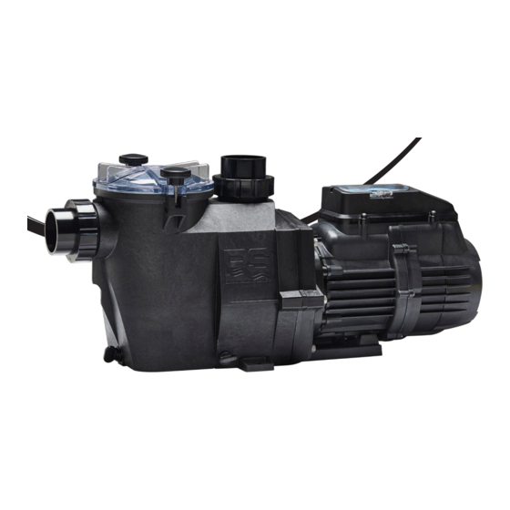
- Page 1 Instruction Manual 1hp & 1.5hp...
- Page 2 THERAFLO REPLACEMENT PARTS DIAGRAM THERAFLO REPLACEMENT PARTS DIAGRAM...
- Page 3 THERAFLO REPLACEMENT PARTS TABLE CONTENTS REF NO. PART NO. DESCRIPTION 1 & 2 THERAF4320 Hand Knob Kit for Strainer Cover (inc Hand Knob & IMPORTANT SAFETY INSTRUCTIONS Swivel Nut) THERAF4304 Strainer Cover, Hand Knob Style - Clear THERAF4303 Strainer Cover O-Ring THERAFLO INTRODUCTION THERAF4302 Basket...
-
Page 4: Important Safety Instructions
THERAFLO REPLACEMENT PARTS DIAGRAM IMPORTANT SAFETY INSTRUCTIONS THERAFLO REPLACEMENT PARTS DIAGRAM Before installing or servicing this electrical equipment, disconnect it from the power supply WARNING Read and follow all instructions in this owner’s manual and on the equipment. Failure to follow instructions can cause severe injury and/or death. - Page 5 THERAFLO REPLACEMENT PARTS TABLE THERAFLO REPLACEMENT PARTS TABLE IMPORTANT SAFETY INSTRUCTIONS Before installing or servicing this electrical equipment, disconnect it from the power supply REF NO. PART NO. DESCRIPTION REF NO. PART NO. DESCRIPTION WARNING – Risk of Electric Shock. All electrical 1 &...
- Page 6 THERAFLO REPLACEMENT PARTS DIAGRAM IMPORTANT SAFETY INSTRUCTIONS THERAFLO REPLACEMENT PARTS DIAGRAM Before installing or servicing this electrical equipment, disconnect it from the power supply WARNING – Hazardous Pressure. Pool and spa water circulation systems operate under hazardous pressure during start-up, normal operation, and after pump shut-off. Stand clear of circulation system equipment during pump start-up.
- Page 7 THERAFLO REPLACEMENT PARTS TABLE IMPORTANT SAFETY INSTRUCTIONS THERAFLO REPLACEMENT PARTS TABLE Before installing or servicing this electrical equipment, disconnect it from the power supply REF NO. PART NO. DESCRIPTION REF NO. PART NO. DESCRIPTION WARNING – Suction Entrapment Hazard. The force from suction in 1 &...
- Page 8 The Theraflo TVS swimming pool pump is part of the unique Australian designed Theralux swimming pool sanitation system, which focuses on providing the healthiest swimming pool environments possible for our users. This is achieved through the calibration of hundreds of years industry experience, allowing us to challenge the realms of industry normality.
- Page 9 THERAFLO REPLACEMENT PARTS TABLE THERAFLO INSTALLATION THERAFLO REPLACEMENT PARTS TABLE The Theraflo TVS comes with quick release connecting unions on both the inlet REF NO. PART NO. DESCRIPTION REF NO. PART NO. DESCRIPTION and outlet which simplifies the installation process. It also allows the user to 1 &...
- Page 10 THERAFLO REPLACEMENT PARTS DIAGRAM THERAFLO START UP THERAFLO REPLACEMENT PARTS DIAGRAM Once the glue has had the required amount of setting time, check that both the inlet and outlet connection points are hand tight. At this point, it is necessary to prime the pump wet end. This can be done by unscrewing the 2 locking knobs &...
- Page 11 THERAFLO REPLACEMENT PARTS TABLE THERAFLO CONTROL PANEL THERAFLO REPLACEMENT PARTS TABLE EXPLANATION REF NO. PART NO. DESCRIPTION REF NO. PART NO. DESCRIPTION 1 & 2 THERAF4320 Hand Knob Kit for Strainer Cover (inc Hand Knob & 1 & 2 THERAF4320 Hand Knob Kit for Strainer Cover (inc Hand Knob &...
- Page 12 THERAFLO REPLACEMENT PARTS DIAGRAM THERAFLO TRUE VARIABLE THERAFLO REPLACEMENT PARTS DIAGRAM SPEED CONTROL The Theraflo TVS has 3 factory set motor speeds: ECO, MED & HIGH. The buttons for each speed can be found on the control pad and also has a corresponding LED light to signify the current speed.
- Page 13 Only qualified personnel should attempt to replace the shaft seal. Contact your THERAF4317 Mounting Foot Cap Screw (set of 2) THERAF4317 Mounting Foot Cap Screw (set of 2) local Authorised Theralux Service Centre if you have any questions. THERAF4316B Mounting Bracket, hps style THERAF4316B Mounting Bracket, hps style »...
- Page 14 THERAFLO REPLACEMENT PARTS DIAGRAM THERAFLO REPLACEMENT PARTS DIAGRAM Removing the Ceramic Seat 1. Remove the seal plate (item 23) from the motor mounting plate (item 25). 2. Press the ceramic seat with rubber cup out of the seal plate (item 23). If tight, use a small screwdriver to tap the seal out from the back side of the seal plate.
- Page 15 THERAFLO REPLACEMENT PARTS DIAGRAM THERAFLO REPLACEMENT PARTS TABLE THERAFLO REPLACEMENT PARTS TABLE REF NO. PART NO. DESCRIPTION REF NO. PART NO. DESCRIPTION 1 & 2 THERAF4320 Hand Knob Kit for Strainer Cover (inc Hand Knob & 1 & 2 THERAF4320 Hand Knob Kit for Strainer Cover (inc Hand Knob &...
- Page 16 THERAFLO REPLACEMENT PARTS DIAGRAM THERAFLO REPLACEMENT PARTS TABLE THERAFLO REPLACEMENT PARTS DIAGRAM REF NO. PART NO. DESCRIPTION 1 & 2 THERAF4320 Hand Knob Kit for Strainer Cover (inc Hand Knob & Swivel Nut) THERAF4304 Strainer Cover, Hand Knob Style - Clear THERAF4303 Strainer Cover O-Ring THERAF4302...
- Page 17 THERAFLO REPLACEMENT PARTS TABLE THERAFLO CARE & MAINTENANCE THERAFLO REPLACEMENT PARTS TABLE It is strongly advised that you check the hair and lint pot basket area regularly for REF NO. PART NO. DESCRIPTION REF NO. PART NO. DESCRIPTION any debris. If debris is found within the basket, you should empty the basket, as 1 &...
- Page 18 Our warranty covers manufacturing faults, not wear and tear. We will, at our discretion, repair or replace the faulty material or part. It is your responsibility to notify Theralux at the earliest possible time of any issues found within the warranty period.
- Page 19 THERAFLO REPLACEMENT PARTS TABLE NOTES THERAFLO REPLACEMENT PARTS TABLE REF NO. PART NO. DESCRIPTION REF NO. PART NO. DESCRIPTION 1 & 2 THERAF4320 Hand Knob Kit for Strainer Cover (inc Hand Knob & 1 & 2 THERAF4320 Hand Knob Kit for Strainer Cover (inc Hand Knob & Swivel Nut) Swivel Nut) THERAF4304...
- Page 20 International Quadratics www.theralux.com.au 1300 131 788 sales@interquad.com.au This user manual shall not be reproduced without the prior permission of International Quadratics.
Need help?
Do you have a question about the Theraflo TVS 1hp and is the answer not in the manual?
Questions and answers