Table of Contents
Advertisement
Available languages
Available languages
Quick Links
Advertisement
Chapters
Table of Contents

Related Manuals for Promax PD-183


Summary of Contents for Promax PD-183
- Page 1 MULTÍMETRO DIGITAL DIGITAL MULTIMETER PD-183 - 0 MI1425 -...
- Page 3 NOTAS SOBRE SEGURIDAD Antes de manipular el equipo leer el manual de instrucciones y muy especialmente el apartado PRESCRIPCIONES DE SEGURIDAD. El símbolo sobre el equipo significa "CONSULTAR EL MANUAL DE INSTRUCCIONES". En este manual puede aparecer también como símbolo de advertencia o precaución. Recuadros de ADVERTENCIAS Y PRECAUCIONES pueden aparecer a lo largo de este manual para evitar riesgos de accidentes a personas o daños al equipo u otras propiedades.
-
Page 5: Table Of Contents
ANUAL DE INSTRUCCIONES. PD-183 Í N D I C E INTRODUCCIÓN ...............1 Especificaciones ................1 PRESCRIPCIONES DE SEGURIDAD........7 Generales ..................7 Ejemplos descriptivos de las categorías de Sobretensión....8 Descripción de mandos y elementos .........9 INSTRUCCIONES DE FUNCIONAMIENTO......11 Función de auto apagado ..............11 Indicación acústica de conexión errónea........11... - Page 6 ANUAL DE INSTRUCCIONES. PD-183...
-
Page 7: Introducción
ANUAL DE INSTRUCCIONES. PD-183 MULTÍMETRO DIGITAL PD-183 1 INTRODUCCIÓN El PROMAX PD-183 se ha diseñado de acuerdo con los requisitos más estrictos de calidad, para satisfacer los estándares de seguridad más rigurosos. Reúne las características básicas de un instrumento profesional, tales como alta precisión, fiabilidad y una amplia escala de medidas. - Page 8 ANUAL DE INSTRUCCIONES. PD-183 Indicación de pila baja: Se visualiza el símbolo " " cuando el voltaje de la batería cae por debajo del nivel de funcionamiento. Auto desconexión: 45 min. Aproximadamente. Temperatura de funcionamiento: 0°C a 50°C con una humedad relativa de <...
- Page 9 ANUAL DE INSTRUCCIONES. PD-183 Tensión DC Impedancia Escala Resolución Precisión de entrada 200mV 10μV 100μV ±(0,05% lect + 3 díg) 10MΩ 200V 10mV 1000V 100mV Protección contra sobrecarga: 500V DC / 350V RMS en la escala 200mV. 1000V DC / 750V RMS en las demás escalas.
- Page 10 ANUAL DE INSTRUCCIONES. PD-183 Corriente DC Escala Resolución Precisión Carga de Voltaje 200μA 10nA 300mV 100nA 300mV ±(0,5% lect + 5 díg) 20mA 1μA 300mV 200mA 10μA 600mV 20A** ±(2,0% lect + 10 díg) 800mV Protección de sobrecarga: Fusible 500mA/500V en la entrada de mA.
- Page 11 ANUAL DE INSTRUCCIONES. PD-183 Resistencia Voltios del circuito Escala Resolución Precisión abierto ±(0,25% lect + 10 d) 3,3Vdc 200Ω 10mΩ ±(0,15% lect + 3 d) 3,3Vdc 2kΩ 0,1Ω ±(0,15% lect + 3 d) 3,3Vdc 20kΩ 1Ω ±(0,15% lect + 3 d) 3,3Vdc 200kΩ...
- Page 12 ANUAL DE INSTRUCCIONES. PD-183 Test de Lógica Umbral Anchura Repetición Tiempo de impulso impulso subida Lógica 1 Lógica 0 (mínimo) (máx) (máx) (Hi) (Lo) 25ns 1Mpps 2,8V±0,8V 0,8V±0,5V 10μSec Test de voltaje: 5VDC >20% y <80% Ciclo de función: Respuesta de...
-
Page 13: Prescripciones De Seguridad
ANUAL DE INSTRUCCIONES. PD-183 2 PRESCRIPCIONES DE SEGURIDAD 2.1 Generales • Este equipo puede ser utilizado en instalaciones con Categoría de Sobretensión III y ambientes con Grado de Polución 2. • Al emplear cualquiera de los siguientes accesorios debe hacerse sólo... -
Page 14: Ejemplos Descriptivos De Las Categorías De Sobretensión
ANUAL DE INSTRUCCIONES. PD-183 • Simbología de seguridad: 2.2 Ejemplos descriptivos categorías Sobretensión Cat I Instalaciones de baja tensión separadas de la red. Cat II Instalaciones domésticas móviles. Cat III Instalaciones domésticas fijas. Cat IV Instalaciones industriales. Página 8 07/2015... -
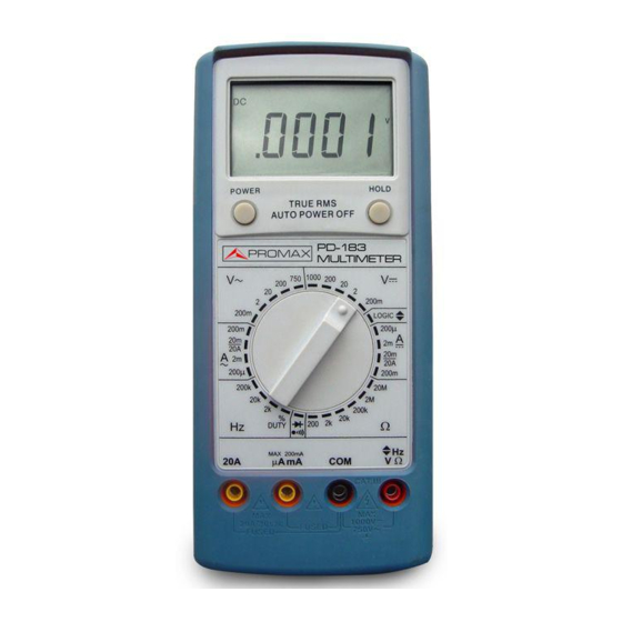
Page 15: Descripción De Mandos Y Elementos
ANUAL DE INSTRUCCIONES. PD-183 3 DESCRIPCIÓN DE MANDOS Y ELEMENTOS Figura.-1: Panel frontal 1. Pantalla LCD Pantalla de 4-1/2 dígitos (máximo 19999 cuentas) con coma decimal automática, e indicadores de función seleccionada, unidad de medida, valor lógico y de baja carga de pila. - Page 16 ANUAL DE INSTRUCCIONES. PD-183 3. Selector rotativo Este interruptor rotatorio selecciona la función y el rango deseados. 4. Terminal 20A de entrada Este es el terminal positivo de la entrada para la medida de corriente (AC ó DC) hasta 20A. La conexión se realiza utilizando la punta de prueba de color rojo.
-
Page 17: Instrucciones De Funcionamiento
ANUAL DE INSTRUCCIONES. PD-183 4 INSTRUCCIONES DE FUNCIONAMIENTO Antes de hacer cualquier medida examine siempre el instrumento y los accesorios usados con el instrumento para detectar posibles daños, contaminación (excesiva suciedad, grasa, etc.) y otros defectos. Examine los terminales de las puntas de prueba por si el aislante está... -
Page 18: Medidas Del Verdadero Valor Eficaz Rms
ANUAL DE INSTRUCCIONES. PD-183 4.3 Medidas del verdadero valor eficaz rms Este multímetro permite la medida directa del verdadero valor eficaz RMS de una señal. Ésta es la mejor manera de medir los parámetros utilizados en las medidas relativas a la potencia. - Page 19 ANUAL DE INSTRUCCIONES. PD-183 Este multímetro está acoplado en AC y medirá exactamente la componente RMS de alterna de la señal de entrada. La función de tensión DC medirá el componente de continua. Para obtener el valor verdadero RMS total, mida la componente AC RMS mediante la función de tensión AC y la componente DC mediante la función de...
-
Page 20: Medidas De Tensión
ANUAL DE INSTRUCCIONES. PD-183 4.4 Medidas de tensión ADVERTENCIA: Para evitar una posible descarga eléctrica, daños al instrumento y/o daños de equipo, no intente realizar medidas de tensión si el voltaje es superior a 1000Vdc/750Vac. 1000Vdc y 750Vac son las tensiones máximas que este instrumento puede medir. -
Page 21: Medidas De Corriente
ANUAL DE INSTRUCCIONES. PD-183 4.5 Medidas de corriente Éstas se hacen en serie con el circuito de prueba. Toda la corriente que se medirá atraviesa el multímetro. ADVERTENCIA: No intente medir corrientes en circuitos de alta potencia capaces de entregar más de 600V. Dado que el fusible está... - Page 22 ANUAL DE INSTRUCCIONES. PD-183 NOTA: Si se selecciona la escala de 20A entonces debe utilizarse el conector de entrada de 20A en el paso 2 descrito anteriormente. Si se seleccionan las escalas de μA, ó mA deberá utilizarse el conector de entrada de mA en el paso 2 descrito anteriormente.
-
Page 23: Medidas De Resistencias
ANUAL DE INSTRUCCIONES. PD-183 4.6 Medidas de resistencias ADVERTENCIA: Desconecte el circuito de prueba y descargue todos los condensadores antes de intentar realizar medidas de resistencias. Si un voltaje externo está presente en algún componente, será imposible efectuar una medida exacta de la resistencia de ese componente. -
Page 24: Prueba De Diodos
ANUAL DE INSTRUCCIONES. PD-183 4.8 Prueba de diodos ADVERTENCIA: Las medidas se deben hacer solamente con el circuito bajo prueba desconectado. 1. Fije el conmutador rotativo a la posición ( 2. Siga el paso 3 de las medidas de resistencias. - Page 25 ANUAL DE INSTRUCCIONES. PD-183 2. Conecte la punta de prueba roja en el conector de V/ Ω/ Hz y la punta de prueba negra en el conector COM. 3. Conecte las puntas de prueba en el punto de medida y lea la frecuencia en la pantalla.
- Page 26 ANUAL DE INSTRUCCIONES. PD-183 Página 20 07/2015...
-
Page 27: Mantenimiento
ANUAL DE INSTRUCCIONES. PD-183 5 MANTENIMIENTO 5.1 Limpieza del multímetro Limpie la caja de vez en cuando con un paño húmedo. No utilice disolventes productos químicos, productos limpiadores, abrasivos o detergentes. 5.2 Substitución de la pila ADVERTENCIA: Desconectar todas las puntas de prueba antes de iniciar el proceso de sustitución de la pila. -
Page 28: Substitución De Los Fusibles
ANUAL DE INSTRUCCIONES. PD-183 5.3 Substitución de los fusibles ADVERTENCIA: Desconectar todas las puntas de prueba antes de iniciar el proceso de sustitución de los fusibles. Apagar el equipo. Los fusibles están ubicados dentro del equipo. Para substituirlos siga las siguientes instrucciones: 1. - Page 29 USER’S MANUAL. PD-183 T A B L E OF C O N T E N T S Introduction ................1 Specifications ..................1 General safety rules ..............7 General ....................7 Descriptive Examples of Over-Voltage Categories......8 Description of controls and elements.........9 Operating Instructions ..............11 Auto power off .................11...
- Page 30 USER’S MANUAL. PD-183...
-
Page 31: Introduction
USER’S MANUAL PD-183 DIGITAL MULTIMETER PD-183 1 INTRODUCTION The PROMAX PD-183 has been designed in agreement with the strictest requirements of quality, to agree to the more rigorous security standards. Joining the basic characteristics of a professional instrument, such as a high precision, reliability and a wide range of measures. - Page 32 USER’S MANUAL PD-183 Operating environment: 0°C to 50°C at < 70% R.H. Altitude: 2000m Battery: Single 9Volt battery 6F22. Size (H×W×D): (198×90×44mm) Weight: Approx. 400 g including battery. Accesorios Test leads PP-08. Spare fuse 9V 6F22 alkaline battery (included) User’s Manual 0 MI1425 *Accuracy is given as ±([% of reading] + [number of least significant digits]) at...
- Page 33 USER’S MANUAL PD-183 DC Volts Input Range Resolution Accuracy Impedance 200mV 10μV 100μV ±(0.05% rdg + 3 d) 10MΩ 200V 10mV 1000V 100mV Overload Protection: 500VDC / 350V RMS on 200mV range. 1000VDC / 750V RMS on all other ranges.
- Page 34 USER’S MANUAL PD-183 DC Current Resolution Range Accuracy Burden Voltage 200μV 10nA ±(0.5% rdg + 5 d) 300mV 100nA ±(0.5% rdg + 5 d) 300mV 20mA 1μA ±(0.5% rdg + 5 d) 300mV 200mA 10μA ±(0.5% rdg + 5 d)
- Page 35 USER’S MANUAL PD-183 Resistance Open Circuit Resolution Range Accuracy Volts ±(0.25% rdg + 10 d) 3.3Vdc 200Ω 10mΩ ±(0.15% rdg + 3 d) 3.3Vdc 2kΩ 0.1Ω ±(0.15% rdg + 3 d) 3.3Vdc 20kΩ 1Ω ±(0.15% rdg + 3 d) 3.3Vdc 200kΩ...
- Page 36 USER’S MANUAL PD-183 Logic Test Pulse Thresholds Pulse Rise Pulse Rep Width Logic 1 Logic 0 (máx) (máx) (min) (Hi) (Lo) 1Mpps 25ns 2.8V±0.8V 0.8V±0.5V 10μSec Test Voltage: 5VDC >20% and <80% Duty Cycle: Frequency Response: 20MHz Indication: 40msec beep at logic 1 (Hi)
-
Page 37: General Safety Rules
USER’S MANUAL PD-183 GENERAL SAFETY RULES 2.1 General • This equipment can be used in Overvoltage Category III installations and Pollution Degree 2 environments. • When using some of the following accessories use only the specified ones to ensure safety:... -
Page 38: Descriptive Examples Of Over-Voltage Categories
USER’S MANUAL PD-183 • Symbols related with safety. 2.2 Descriptive Examples of Over-Voltage Categories Cat I Low voltage installations isolated from the mains Cat II Portable domestic installations Cat III Fixed domestic installations. Cat IV Industrial installations. Page 8 07/2015... -
Page 39: Description Of Controls And Elements
USER’S MANUAL PD-183 3 DESCRIPTION OF CONTROLS AND ELEMENTS. Figure.-1: Front Panel. 1. LCD Display. 4-1/2 digit (19999 maximum) with automatic decimal point analog bar graph, low battery and full annunciators for function and unit of measurement. 07/2015 Page 9... - Page 40 USER’S MANUAL PD-183 2. Power Button. This switch is used to turn meter on or off. The equipment also will automatically power on by switching the rotary selector position. 3. Selector Rotary. This rotary switch selects function and range needed.
-
Page 41: Operating Instructions
USER’S MANUAL PD-183 4 OPERATING INSTRUCTIONS Before making any measurements always examine the instrument accessories used with instrument damage, contamination (excessive dirt, grease, ect.) and defects. Examine the test leads for cracked or frayed insulation and make sure the lead plugs fit snugly into the instrument jacks. If any abnormal conditions exist do not attempt to make any measurements. - Page 42 USER’S MANUAL PD-183 The relationship between the total true RMS (AC+DC) and the component AC and DC signals is given by the following expression: √ True RMS = (AC RMS Component) + (DC Component) RMS is equivalent to that DC value which dissipates the same amount of power in a resistor.
-
Page 43: Voltage Measurements
USER’S MANUAL PD-183 AC converters of all types are limited by their frequency response and input dynamic range. Measurements of complex waveforms will not be affected by converter bandwidth limitations, provide that all significant AC components contained within the waveforms are within the bandwidth of the converter. -
Page 44: Current Measurements
USER’S MANUAL PD-183 4. When all measurements are completer, disconnect the test leads from the circuit under test. Remove test leads from the multimeter. For DC voltage readings, the RED lead tip should be connected to the positive side of the circuit, the BLACK lead to the negative side. - Page 45 USER’S MANUAL PD-183 2. For measuring currents less than 200mA, connect the RED test lead to the mA input terminal. For measuring currents between 200mA and 20A connect the RED test lead to the 20A terminal. 3. Select the Aac (A~) or Adc (A ) function and the desired range by means of the rotary selector.
-
Page 46: Resistance Measurements
USER’S MANUAL PD-183 7. Never apply a voltage between the COM terminal and current terminals. 8. When switching between current ranges to obtain greater accuracy and better resolution, completely de-energize the circuit to be measured before changing the range. 4.6 Resistance measurements... -
Page 47: Continuity Testing
USER’S MANUAL PD-183 4.7 Continuity testing 1. Select the ( ) position by turning the rotary selector switch. 2. Connect the BLACK and RED test probe tips to the circuit or device under test, making sure it is de-energized first. An acoustic tone will sound if the measured value is lower than 100Ω.. -
Page 48: Frequency And Duty Cycle Measurements
USER’S MANUAL PD-183 5. When a high logic level is measured, it will be indicated in LCD display with value 1, whereas a low logic level is indicated with value 4.10 Frequency and duty cycle measurements 1. Set the rotary selector to the Hz position for the Frequency measurement. -
Page 49: Maintenance
USER’S MANUAL PD-183 5 MAINTENANCE 5.1 Cleaning the multimeter Wipe the case occasionally with a damp cloth. DO NOT use chemicals, cleaning solvents, abrasives or detergents. 5.2 Replacing the battery ADVERTENCIA: Disconnect all the test leads before initiating the fuse replacement process. - Page 50 USER’S MANUAL PD-183 Fuses are located incide the instrument. In order to replace them you must follow these instructions: 1. Unscrew and remove the rear panel using a Phillips suitable screwdriver. 2. Remove old fuses and replace them by the new ones.
- Page 52 PROMAX ELECTRONICA, S. L. Francesc Moragas, 71-75 08907 L'HOSPITALET (Barcelona) SPAIN Tel.: 93 184 77 00; Tel. Intl.: (+34) 93 184 77 02 Fax: 93 338 11 26; Fax. Intl: (+34) 93 338 11 26 http://www.promaxelectronics.com e-mail: promax@promaxelectronics.com...
Need help?
Do you have a question about the PD-183 and is the answer not in the manual?
Questions and answers