Table of Contents
Advertisement
Quick Links
ASSEMBLY AND INSTALLATION INSTRUCTIONS
STEP 1: REVIEW & CHECK
A) CONFIRM DOOR HEIGHT & WIDTH
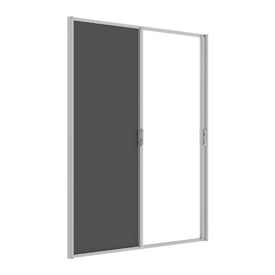
You have purchased a DOUBLE Retractable Screen for an
INSWING door.
HEIGHT: This unit is available in two sizes: Retro and Full-Size.
Please make sure that the screen unit you have purchased
matches your door height.
WIDTH: This screen unit will fit door widths of 6/0 (without
cutting) and 5/10 (Retro Only), 5/4 or 5/0 (with cutting).
If you need additional information on measurements, download
sizing document here: http://bit.ly/SEsizing.
B) PART REVIEW
Verify that the following components are included in the box.
Parts are listed from left to right. See Figure 1A >
1.
Screen Housing marked A and D (1)
2. Screen Housing marked B and C (1)
3. Header (top) Screen Track with locking hardware marked
A and B (1)
4. Sill (bottom) Screen Track with locking hardware marked
C and D (1)
5. Screen Track Covers (2)
6. Mounting Screws for corner and tracks
a. Four - #8 x 3" phillips head tapping screws
b. Five - #8 x 1-1/2" phillips head tapping screws
c. Four - #8 x 5/8" phillips head tapping screws
d. Five - #8 x 1/2" phillips head self-drilling screws
e. Four - #8 x 1" self-drilling screws
7.
Screen Housing Circular Screw Covers (4)
C) TOOLS REQUIRED
•
Level
•
Square
•
Tape Measure
•
Drill
•
Rubber Mallet
www.simplyelegantproducts.com/rts-in
See Figure 1B >
•
Screwdriver: flat head and
Phillips head
•
Pencil
•
Hacksaw
RETRACTABLE SCREEN
DOUBLE INSWING
220-111 (Retro) / 220-112 (Full-Size) / 220-116 (8/0)
FIG. 1A
1
2
3
4
5
6a
6b
6c
6d
6e
7
FIG. 1B
Page 1 of 7
Advertisement
Table of Contents

Summary of Contents for Simply Elegant 220-111
- Page 1 RETRACTABLE SCREEN DOUBLE INSWING 220-111 (Retro) / 220-112 (Full-Size) / 220-116 (8/0) ASSEMBLY AND INSTALLATION INSTRUCTIONS STEP 1: REVIEW & CHECK FIG. 1A A) CONFIRM DOOR HEIGHT & WIDTH You have purchased a DOUBLE Retractable Screen for an INSWING door.
- Page 2 RETRACTABLE SCREEN DOUBLE INSWING 220-111 (Retro) / 220-112 (Full-Size) / 220-116 (8/0) ASSEMBLY AND INSTALLATION INSTRUCTIONS STEP 2: ASSEMBLY PREPARATIONS Very important! Please examine the picture at right for additional details. See Figure 2A > Before proceeding to assembly, please look at the back of the header and sill screen tracks (Items 3 &...
- Page 3 RETRACTABLE SCREEN DOUBLE INSWING 220-111 (Retro) / 220-112 (Full-Size) / 220-116 (8/0) ASSEMBLY AND INSTALLATION INSTRUCTIONS STEP 3: ASSEMBLY FIG. 3A Place all the items from the box on the floor in front of the patio or single door where the single screen is to be installed (colored stickers facing up).
- Page 4 RETRACTABLE SCREEN DOUBLE INSWING 220-111 (Retro) / 220-112 (Full-Size) / 220-116 (8/0) ASSEMBLY AND INSTALLATION INSTRUCTIONS STEP 3: ASSEMBLY (continued) FIG. 3C TIGHTEN We now need to tighten the assembled screen unit. Using the four #8 x 5/8” phillips head tapping screws (Item 6c), lock the screen housing arm to the screen track (Items 3 &...
- Page 5 The screen unit will be mounted directly to the brickmold on the outside of the door frame. If there is no brickmold outside your door frame, you will need to purchase the Simply Elegant Molding Kit (Part #: 100-110). This will ensure that the jamb, head and sill are flush so that the screen unit will operate smoothly.
- Page 6 RETRACTABLE SCREEN DOUBLE INSWING 220-111 (Retro) / 220-112 (Full-Size) / 220-116 (8/0) ASSEMBLY AND INSTALLATION INSTRUCTIONS STEP 4: INSTALLATION (continued) FIG. 4E MOUNT HEAD TRACK TO DOOR FRAME Position the screen frame on the door opening and make sure the two screens meet up in the center correctly with the door.
- Page 7 RETRACTABLE SCREEN DOUBLE INSWING 220-111 (Retro) / 220-112 (Full-Size) / 220-116 (8/0) ASSEMBLY AND INSTALLATION INSTRUCTIONS STEP 4: INSTALLATION (continued) FIG. 4H INSERT REMAINING SCREWS Finish by screwing the screen housing at each corner with the four #8 x 3” screws (Item 6a). See Figure 4H > Cover these screws with four screw covers (Item 7).


Need help?
Do you have a question about the 220-111 and is the answer not in the manual?
Questions and answers