
Subscribe to Our Youtube Channel
Related Manuals for Nexcom VMD 2003

Summary of Contents for Nexcom VMD 2003
- Page 1 NEXCOM International Co., Ltd. Mobile Computing Solutions Vehicle Mount Display VMD 2003 User Manual NEXCOM International Co., Ltd. www.nexcom.com Published November 2018...
-
Page 2: Table Of Contents
11. Mute ...................12 VMD 2003 Mechanical Dimensions ............3 12. Backlight ..................12 Chapter 2: VMD 2003 Hardware Functionality Front Panel Functions ................4 I/O on the Side ..................5 Copyright © 2017 NEXCOM International Co., Ltd. All rights reserved VMD 2003 User Manual... - Page 3 Appendix B: Pin Definition for the ultraONE+ & CVBS Cables ultraONE+ Cable (Female) ..............13 P1 Connector Pinout ................14 P2 Connector Pinout ................14 CVBS Cable (Male) ................15 P5 Connector Pinout ................16 Copyright © 2017 NEXCOM International Co., Ltd. All rights reserved VMD 2003 User Manual...
-
Page 4: Preface
This equipment has been tested and found to comply with the limits for a Class A digital device, pursuant to part 15 of the FCC Rules. VMD 2003 is a trademark of NEXCOM International Co., Ltd. These limits are designed to provide reasonable protection against harmful Intel and Pentium are trademarks of Intel Corporation. - Page 5 0.1% or 1,000ppm, and Polybrominated diphenyl Ethers (PBDE) < 0.1% or 1,000ppm. In order to meet the RoHS compliant directives, NEXCOM has established an engineering and manufacturing task force in to implement the intro- duction of green products. The task force will ensure that we follow the...
-
Page 6: Installation Recommendations
Use the correct screws and do not overly tighten them. ▪ Keep the original packaging and static-protective bag in case the unit has to be returned. Copyright © 2017 NEXCOM International Co., Ltd. All Rights Reserved. VMD 2003 User Manual... -
Page 7: Warranty And Rma
Customers shall enclose the “NEXCOM RMA Service Form” with the ▪ returned packages. Items will be replaced with NEXCOM products if the original one is not ▪ Customers must collect all the information about the problems encoun- able to be repaired. Ex: motherboard, power supply, etc. -
Page 8: Headquarters
ZhongHe District, Beijing, 100094, China New Taipei City, 23586, Taiwan, R.O.C. Tel: +86-10-5704-2680 Tel: +886-2-8226-7796 Fax: +86-10-5704-2681 Fax: +886-2-8226-7792 Email: sales@nexcom.cn Email: sales@nexcom.com.tw www.nexcom.cn www.nexcom.com.tw viii Copyright © 2017 NEXCOM International Co., Ltd. All Rights Reserved. VMD 2003 User Manual... - Page 9 Hui Yin Ming Zun Building Room 1108, Building No. 11, 599 Yunling Road, Putuo District, Shanghai, 200062, China Tel: +86-21-6125-8282 Fax: +86-21-6125-8281 Email: frankyang@nexcom.cn www.nexcom.cn Copyright © 2017 NEXCOM International Co., Ltd. All Rights Reserved. VMD 2003 User Manual...
-
Page 10: Package Contents And Ordering Information
The following information below provides ordering information for Before continuing, verify that the VMD 2003 package that you received VMD 2003. is complete. Your VMD 2003 package should have all the items listed in the following table. P/N: 10VD0200300X0 VMD 2003-BS 8” 800 x 600 Vehicle Display 1000nits w/CVBS x 4... -
Page 11: Chapter 1: Product Introduction
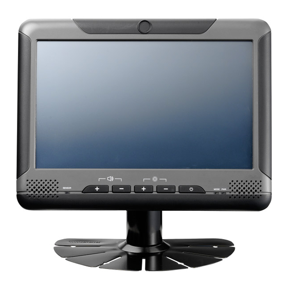
VMD 2003 Overview Key Features ▪ 8” SVGA TFT LCD monitor VMD 2003 is a 8-inch High-brightness TFT LCD monitor with 4 wire resistive ▪ touch, analog cameras supported and ultraONE+ technology. Due to this UltraONE+ technology ▪ unique feature: ultraONE+, VMC 2003 needs to work with the telematics 10M transmission distance computer, which also offers the function of ultraONE+ technology. -
Page 12: Hardware Specifications
Brightness control (+/-) ▪ – CE approval Volume control (+/-) ▪ ▪ FCC Class B Light sensor ▪ 2 x LED indicators ▪ 2 x Built-in speakers (1.2W) Copyright © 2017 NEXCOM International Co., Ltd. All Rights Reserved. VMD 2003 User Manual... -
Page 13: Vmd 2003 Mechanical Dimensions
Chapter 1: Product Introduction VMD 2003 Mechanical Dimensions ▪ 207mm (W) x 173mm (H) x 36.7mm (D) ▪ 0.8kg (1.76lb) 16.5 36.3 Copyright © 2017 NEXCOM International Co., Ltd. All Rights Reserved. VMD 2003 User Manual... -
Page 14: Chapter 2: Vmd 2003 Hardware Functionality
Front Panel Functions VMD 2003 has two modes for video input (Configured through S/W only. Front Panel Please refer to SDK). VMD 2003 has Control Mode (including Auto Mode and Manual Mode) for selecting which video content to be shown on the screen. -
Page 15: I/O On The Side
VMD 2003 will change to the corresponding camera. If there I/O Side are more than one camera powering on, the image on VMD 2003 will show the first number. For example, the priority of CVBS 1 is higher than CVBS 2, therefore, the video content of CVBS 1 will be shown. - Page 16 Chapter 2: VMD 2003 Hardware Functionality Mic-in Line-out USB 2.0 No Function Type A Copyright © 2017 NEXCOM International Co., Ltd. All Rights Reserved. VMD 2003 User Manual...
-
Page 17: Chapter 3: Hardware Installation
VMD 200x series. 1. Fasten the black metal plate onto the rear panel with the 4 screws. 3. Attach and fasten the LCD panel onto the monitor stand. Copyright © 2017 NEXCOM International Co., Ltd. All Rights Reserved. VMD 2003 User Manual... -
Page 18: Assembling The Vesa Mount Plate
1. Remove the 4 screws on the black metal plate. 2. Place the VESA mount plate on the black metal plate and then fasten the four screws. Copyright © 2017 NEXCOM International Co., Ltd. All Rights Reserved. VMD 2003 User Manual... -
Page 19: Chapter 4: Connector Pin Definitions
Connector CVBS Input Connector Male Female Definition Definition Definition Definition USB DATA- CVBS_INPUT0 CVBS_INPUT1 LVDS L- PWR_BTN CVBS_INPUT2 CVBS_INPUT3 24V_VIN USB DATA+ LVDS L+ 24V_DETECT Copyright © 2017 NEXCOM International Co., Ltd. All Rights Reserved. VMD 2003 User Manual... -
Page 20: Appendix A: Software Utility For Vmd 2003
2. Hardware Version Shows the PCB version. 3. DTP Version Shows the Data Transmission Protocol (DTP) version. 4. MCU Boot Loader Version Shows the MCU boot loader version. Copyright © 2017 NEXCOM International Co., Ltd. All Rights Reserved. VMD 2003 User Manual... -
Page 21: Supply Voltage
VMD 2003 will change to the corresponding camera. If there are more than one camera powering on, the image on VMD 2003 will show the first number. For example, the priority of CVBS 1 is higher than CVBS 2, 7. -
Page 22: Mute
For example, if the default brightness of backlight (8-level) in the sunshine is not enough, users can set the Backlight to +2. Then the default brightness of backlight will become 10-level. Copyright © 2017 NEXCOM International Co., Ltd. All Rights Reserved. VMD 2003 User Manual... -
Page 23: Ultraone+ Cable (Female)
The ultraONE+ cable consists of a 9-pin female connector and a 9-pin male connector. The following tables list the pin signals of the P1 connector and its corresponding pin signals to the output P2 connector. Female Male Copyright © 2017 NEXCOM International Co., Ltd. All Rights Reserved. VMC 2003 User Manual... -
Page 24: P1 Connector Pinout
USB DATA- LVDS L- PWR BTN USB DATA+ 24VDC IN USB DATA+ LVDS_GND/USB_GND LVDS L+ 24V_DETECT LVDS L- PWR_GND LVDS L+ 24V_DETECT PWR BTN 24VDC IN PWR_GND Copyright © 2017 NEXCOM International Co., Ltd. All Rights Reserved. VMC 2003 User Manual... -
Page 25: Cvbs Cable (Male)
CVBS Cable (Male) The CVBS cable consists of a 9-pin male connector and multiple output connectors. The following table lists the pin signals of the P5 connector. Male Copyright © 2017 NEXCOM International Co., Ltd. All Rights Reserved. VMC 2003 User Manual... -
Page 26: P5 Connector Pinout
Appendix B: Pin Definition for the ultraONE+ and CVBS Cables P5 Connector Pinout Male Definition Definition CVBS_INPUT0 CVBS_INPUT1 CVBS_INPUT2 CVBS_INPUT3 Copyright © 2017 NEXCOM International Co., Ltd. All Rights Reserved. VMC 2003 User Manual...
Need help?
Do you have a question about the VMD 2003 and is the answer not in the manual?
Questions and answers