
Related Manuals for Uchida Yoko BC-10

Summary of Contents for Uchida Yoko BC-10
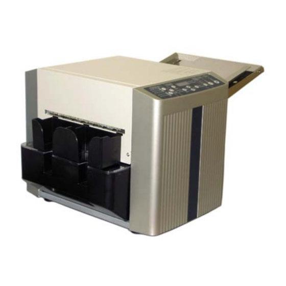
- Page 1 Uchica BC10 Business Card Cutter Service Manual Provided By http://www.MyBinding.com http://www.MyBindingBlog.com...
- Page 2 UCHIDA BC-10 BUSINESS CARD CUTTER SERVICE MANUAL...
-
Page 3: Table Of Contents
CONTENTS 1. EXPLANATION OF SYMBOLS ·························································· 2. SAFETY INSTRUCTIONS ··································································· 3. DEFINITION OF THE PARTS ····························································· 3-1. Overview ·························································································· 3-2. Behind the Front Cover ································································ 3-3. Behind the Rear Cover ································································· 3-4. Behind the Front Panel ································································· 3-5. Behind the Rear Panel ·································································· 3-6. -
Page 4: Explanation Of Symbols
6. TROUBLESHOOTING ········································································· 7. ADJUSTMENT ······················································································ 7-1. To fix the paper skews ·································································· 7-2. Adjustment with DIP Switches ··················································· 7-2-1. To adjust the Top Margin ······················································ 7-2-2. To adjust the Card Length ···················································· Please follow safety instructions on labels attached on the machine when you do service. Be sure to turn off the Power Switch and remove the plug before touching the internal parts of the machine. -
Page 5: Safety Instructions
Card Stacking Box has been removed. Do not expose the BC-10 to rain or wet conditions in order to avoid fires or electric shock. If you notice a strange sound or smell while the BC-10 is running, turn off the Power Switch immediately and remove the plug. - Page 6 Do not connect the power cord to an outlet when the plug is dusty. Make sure the plug fits completely into the outlet. Do not use a power cord that is not attached to the BC-10. Do not use the attached power cord for other use.
- Page 7 Do not put the BC-10 in an unstable place in order to avoid the risk of falling down. Remove the plug from the outlet if the BC-10 will not be in use for a long period. Never use the cord to pull the plug from an outlet.
-
Page 8: Definition Of The Parts
3. DEFINITION OF THE PARTS 3-1. Overview 3-1-1 Card Stacking Box Trash Box Front Cover Operation Panel Upper Cover Paper Feeder Unit Power Inlet Power Switch 3-1-2... -
Page 9: Behind The
3-2. Behind the Front Cover Cutter Unit Left Frame Mainboard Front Cover 3-2-1 Operation Panel PCB Operation Panel Harness 3-2-2... -
Page 10: Behind The Rear Cover
3-3. Behind the Rear Cover Right Frame Cutter Unit Pulley to drive Conveying Rollers Timing Belt Stepping Motor 3-3-1 3-4. Behind the Front Panel 3-4-1 Stepping Motor Trash Box Detector DC Power Supply Power Inlet Power Switch Front Panel... -
Page 11: Behind The Rear Panel
3-5. Behind the Rear Panel Slitter Unit Trash Box 3-5-1 3-6. Under the Upper Cover 3-6-1 Upper Cover Opening Detector 3-7-1 S3 Sensor Cutter Unit Cover... -
Page 12: How To Detach The Covers
4. HOW TO DETACH THE COVERS WARNING: Be sure to turn the power off before removing any panel or cover. 4-1. To remove the Front Cover: 1. Turn off the Power Switch. 2. Move the machine to the verge of the desk (4-1-2). 4-1-1 4-1-2 3. - Page 13 5. Remove the two M3 Setscrews from the Rear Panel. 4-1-5 4-1-6 6. Take off the Rear Panel. 7. Remove the M3 Setscrew (4-1-8). 4-1-7 4-1-8...
- Page 14 8. Take off the Front Cover. 4-1-9 9. Pull out the Operation Panel harness from the Mainboard. 4-1-10...
-
Page 15: To Remove The Rear Cover
4-2. To remove the Rear Cover: 1. Turn off the Power Switch. 2. Move the machine to the verge of the desk. 3. Loosen the M3 Setscrews under the Rear Cover. 4-2-1 4-2-2 4. Open the Upper Cover. 5. Remove the M3 Setscrew. 4-2-3... - Page 16 6. Remove the two M3 Setscrews from the Rear Panel. 4-2-4 4-2-5 7. Take off the Rear Panel. 8. Remove the M3 Setscrew (4-2-7). 4-2-6 4-2-7...
- Page 17 9. Take off the Rear Cover. There is no harness behind the Rear Cover. 4-2-8...
-
Page 18: To Take Off The Front Panel
4-3. To take off the Front Panel: WARNING: Be sure to pull out the Power Cord before removing the Front Panel in order to avoid the risk of electric shock. 1. Turn off the Power Switch. 2. Pull out the Power Cord from the Power Inlet. There is a DC Power Supply behind the Front Panel. - Page 19 5. Remove the two M3 Setscrews in the upper part of the Panel. 4-3-5 4-3-6 6. Take off the Front Panel. Behind the Panel, there are harnesses connected to the Power Inlet and Power Switch. 4-3-7 4-3-8...
-
Page 20: To Take Off The Rear Panel
4-4. To take off the Rear Panel: 1. Turn off the Power Switch. 4-4-1 2. Remove the two M3 Setscrews from the Rear Panel. 4-4-2 4-4-3 3. Take off the Rear Panel. 4-4-4... -
Page 21: Main Parts
5. MAIN PARTS 5-1. Pressure Roller Unit To remove the Pressure Roller Unit: 1. Open the Upper Cover. 2. Lift the handle. Upper Cover Pressure Roller Unit 5-1-1 5-1-2... -
Page 22: I/O Ports On The Mainboard
5-2. I/O Ports on the Mainboard CN2: S3 Sensor CN3: Cutter Sensor CN1: S2 Sensor CN4: Trash Box Detector CN9: Operation Panel CN5: Slitter Detectors CN6: Upper Cover Opening Detector CN7: S1 Sensor CN13: Slitter Motor CN12: Cutter Motor CN11: Pick-up Motor CN10: Stepping Motor CN8: DC Power Supply 5-2-1... -
Page 23: Separate Pad
5-3. Separate Pad The Paper Feeder Unit can be swung only 30° for safety’s sake. When you replace the pad, insert a screwdriver between the Paper Feeder Unit and Paper Induction Deck to keep the Paper Feeder Unit open. Paper Feeder Unit Separate Pad Paper Induction Deck 5-3-1... -
Page 24: S1 Sensor And S2 Sensor
5-4. S1 Sensor and S2 Sensor To replace the S1 or S2 sensor: 1. Remove the Stopper Pin located next to the Hinge Pin on the left frame so that you can swing up the Paper Feeder Unit wider than 30°. 2. -
Page 25: Dc Power Supply
5-5. DC Power Supply To remove the DC Power Supply: 1. Take off the Front Panel (See 4-3). 2. Remove the Setscrews on both frames. 3. Take off the Power Supply Cover. 5-5-1 5-5-2 Power Supply Cover Setscrew Setscrew Power Switch Front Panel 4. -
Page 26: Pick-Up Roller
5-6. Pick-up Roller To replace the Pick-up Roller: 1. Swing up the Paper Feeder Unit. 2. Keep the Paper Feeder Unit open with a screwdriver (See 5-3). 3. Remove the Setscrew and pull out the Roller. 5-6-1 Paper Feeder Unit Setscrew Pick-up Roller 4. -
Page 27: Pick-Up Motor
5-7. Pick-up Motor To remove the Pick-up Motor: 1. Remove the two panels on the Paper Feeder Unit. Panels 5-7-1 5-7-2 2. Remove the Setscrews and lift the Pick-up Motor assembly. 5-7-3 Paper Feeder Unit Pick-up Motor Assembly Pick-up Motor Pick-up Roller 5-7-4... -
Page 28: Stepping Motor
5-8. Stepping Motor To remove the Stepping Motor: 1. Disconnect the harness from the Main Board. 2. Remove the M4 Nuts. Take care not to drop the motor. Stepping Motor Stepping Motor harness 5-8-1 5-8-2 Stepping Motor M4 Nuts... -
Page 29: Cutter Unit
5-9. Cutter Unit To remove the Cutter Unit: 1. Pull out the Cutter Motor harness (CN12) and Cutter Sensor harness (CN3) from the Mainboard (See 5-2). 2. Remove the Setscrews with a hexagon wrench (5-9-1). To set the Cutter Unit: 1. -
Page 30: Slitter Unit
5-10. Slitter Unit To remove the Slitter Unit: 1. Open the Upper Cover. 2. Remove the M4 Setscrews from the Slitter Unit. 3. Remove the M3 Setscrews from the Rear Panel and take off the Panel from the machine. Upper Cover Setscrews Setscrews 5-10-1... - Page 31 4. Pull out the Slitter Motor harness from the Connector. Harness Connector Slitter Unit 5-10-5 5-10-4 5. Hold the both sides of the Slitter Unit and swing up to remove it. 5-10-6 5-10-7 5-10-8...
- Page 32 Turn the power back on after seven seconds. 2. The BC-10 does not There is an error code in the Clear the error and restart. work when you press Display.
- Page 33 The sheets get stuck together Fan the stack of sheets and because of static electricity. reload. The BC-10 is not grounded. Make sure the machine is grounded. The Separate Pad is worn out. Replace the Separate Pad. 6. The BC-10 stops in The Cutter blades have got Replace the Cutter Unit.
- Page 34 Keep the humidity between 50 and 80%. Make sure the machine is grounded. The BC-10 is out of order. Call for service. 11. Finished cards do The BC-10 is not grounded Make sure the machine is...
- Page 35 *1, 2, 3, and 13: If all of the items in each section have been checked and the problems are still unresolved, the BC-10 needs to be repaired. If problems continue after checking all the items above, call for service.
- Page 36 7. ADJUSTMENT 7-1. To fix the paper skews: 1. Make sure the Paper Feeder Tray is set properly. Hopper Plate Left Paper Guide Right Paper Guide 7-1-1 2. While holding the M3 Nut under the Paper Feeder Tray, loosen the Left Paper Guide Adjusting Screw.
- Page 37 If the above procedure does not work, loosen the Setscrews of the Pick-up Motor Assembly and adjust the alignment. 7-1-4 Paper Feeder Unit Pick-up Motor Assembly Pick-up Roller...
- Page 38 7-2. Adjustment with DIP Switches There are two sets of DIP Switches in the left of the Mainboard. Note: Do not change the setting of the SW1 DIP Switches. If you change the setting, the machine will not work properly. All the SW1 DIP Switches must be set to “0 (or Off).” 7-2-2 7-2-1 Do not change the setting.
- Page 39 7-2-1. To adjust the Top Margin: You can adjust the Top Margin with the SW2 DIP Switches. You have 16 steps (1 step: 0.125mm) by setting four toggle switches (#5, #6, #7 and #8). See the table 7-A. Note: Changes of the DIP Switches affect the Top Margins of all Cutting Modes. Table 7-A: Switch settings for Top Margin Adjustment (0=Off, 1=On) Adjusting amount (mm) -1.000...
- Page 40 7-2-2. To adjust the Card Length: You can adjust the Card Length with the SW2 DIP Switches. You have 16 steps (1 step: 0.125mm) by setting four toggle switches (#1, #2, #3 and #4). See the table 7-B. Note: Changes of the DIP Switches affect the Card Lengths of all Cutting Modes. Table 7-B: Switch settings for Card Length Adjustment (0=Off, 1=On) Adjusting amount (mm) -1.000...
Need help?
Do you have a question about the BC-10 and is the answer not in the manual?
Questions and answers