Table of Contents
Advertisement
Quick Links
Advertisement
Table of Contents

Related Manuals for Telos Alliance Omnia MPX Node

Summary of Contents for Telos Alliance Omnia MPX Node
- Page 1 Omnia MPX Node ® MPX Over IP at Extremely Low Data Rates Installation & User’s Guide Version 1.1 October, 2019 2001-00522-000 OMNIA MPX NODE DECODER 2001-00529-000 OMNIA MPX NODE ENCODER TelosAlliance.com P/N: 1490-00211-001 --- OMNIA MPX NODE MANUAL...
- Page 2 Linear Acoustic®, 25-Seven Systems®, and Minnetonka Audio®. We’re here to help you make your work truly shine. We hope that you enjoy your Telos Alliance product for many years to come and won’t hesitate to let us know if we can help in any way.
-
Page 3: Table Of Contents
Table of Contents User Warnings and Cautions We support you… Warranty Introduction Overview About the μMPX Codec A Distinction from L/ R signals Quick Start Instructions Obtaining an IP address Logging In Use Cases & Applications Simple STL: Use with Any FM Processor Omnia 9 as MPX Encoder One Processor to Many Transmitters Use with private networks, and IP radios... - Page 4 User Profile User Information Name Email Username Password Update Profile Logging In for the first time Password & Config Reset Logout Using the GUI GUI Tips System Setup Network Setup Net Mode Network Address Network Mask Network 1 & 2 Gateway DNS Server SAVE Hostname...
- Page 5 Encoder Setup µMPX (MicroMPX) Encoder Settings MPX Input Level Clip Indicator Bitrate Streams Stream Error Correction Keyframe interval Error Correction size/delay Error Correction Overhead Rate Limiter (On/Off) Limit Rate Below Encoder Dashboard Decoder Setup µMPX (MicroMPX) Decoder Settings MPX Output Level Stream Receiver Stream Delay Test Signal...
- Page 6 Rear Panel Composite GPIO NET1 NET2 12VDC Input Internal Switch Settings DIP-switch Access Identifying Switches Encode / Decode Mode (Switch bank 1) Impedance / Gain (Switch bank 2) Technical Notes Firewall and Security Tilt Correction Cooling Rack Mounting Rack Mount kit Short rack ear Long rack ear Revision 2 “L”...
-
Page 7: User Warnings And Cautions
OMNIA MPX NODE MANUAL V1.1-OCTOBER 2019 | User Warnings and Cautions The installation and service instructions in this manual are for use by qualified personnel only. To avoid electric shock, do not perform any servicing other than that contained in the operating instructions unless you are qualified to do so. - Page 8 VIII OMNIA MPX NODE MANUAL V1.1-OCTOBER 2019 | USA CLASS A COMPUTING DEVICE INFORMATION TO USER WARNING: This equipment generates, uses, and can radiate radio-frequency energy. If it is not installed and used as directed by this manual, it may cause interference to radio com- munication.
-
Page 9: We Support You
All versions, claims of compatibility, trademarks, etc. of hardware and software products not made by The Telos Alliance which are mentioned in this manual or accompanying ma- terial are informational only. The Telos Alliance makes no endorsement of any particular product for any purpose, nor claims any responsibility for operation or accuracy. -
Page 10: Warranty
TelosAlliance.com/Omnia Service You must contact Telos Alliance before returning any equipment for factory service. We will need your unit’s serial number, located on the back of the unit. We will issue a return authorization number, which must be written on the exterior of your shipping container. -
Page 11: Introduction
Introduction Overview The Omnia MPX Node is a purpose-built broadcast codec for transporting FM composite (MPX) signals over IP networks. Like its namesake (the classic Axia xNode), Omnia MPX Node is a building block technology that helps stations leverage the growing power and capability of data networking. -
Page 12: A Distinction From L/ R Signals
OMNIA MPX NODE MANUAL V1.1-OCTOBER 2019 | 1. Coding artifacts produced by stereo codecs require additional processing (post transport) to correct overshoots and other errors prior to stereo generation. 2. Artifacts occurring in μMPX coding manifest as FM noise and go unnoticed. -
Page 13: Quick Start Instructions
OMNIA MPX NODE MANUAL V1.1-OCTOBER 2019 | Quick Start Instructions MPX Node is a computing appliance that interfaces to audio processing and FM transmis- sion equipment. Installation and proper operation requires you have some basic knowl- edge of computer networking, firewalls, port management, and other general computer skills, in addition to your radio broadcast knowledge. -
Page 14: Logging In
OMNIA MPX NODE MANUAL V1.1-OCTOBER 2019 | 4. If you don’t have a DHCP server on your network, you can enter a static IP address from the front panel. Press and hold the bottom front panel button for 10 seconds until you see the Setup page. - Page 15 OMNIA MPX NODE MANUAL V1.1-OCTOBER 2019 | The factory default user name is user, the default password is also user. Once you enter this default, you will see the User Profile page. You must enter and save ♦ a new, unique password in order to access other control pages.
-
Page 16: Use Cases & Applications
OMNIA MPX NODE MANUAL V1.1-OCTOBER 2019 | Use Cases & Applications These diagrams provide a quick snapshot of some of the ways MPX nodes can be used. This list is just a fraction of potential applications for this building block technology. MPX Node can help simplify your transmitter rack, eliminating the need for further processing or stereo generation at the transmitter. -
Page 17: One Processor To Many Transmitters
OMNIA MPX NODE MANUAL V1.1-OCTOBER 2019 | One Processor to Many Transmitters This diagram gets at one of the primary benefits of MPX over IP: each decoder is a “carbon copy” of the main processor. Main sites, backups and repeaters all get the same signal. -
Page 18: Redundant Paths And Backup Scenarios
OMNIA MPX NODE MANUAL V1.1-OCTOBER 2019 | Redundant Paths and Backup Scenarios Dual Encoder, Single Decoder In this illustration, a processor feeds two Encoders. Both Encoders send the same signal over UDP to a single Decoder at the same IP and port address. If one of the links fails, the Decoder picks up the stream from the other Encoder after a brief failover period. -
Page 19: The Front Panel
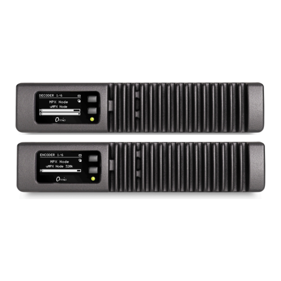
OMNIA MPX NODE MANUAL V1.1-OCTOBER 2019 | The Front Panel The MPX Node front panel consists of two buttons, an LED and a long-life OLED display, housed in a fanless, rugged cast aluminum body with integrated heat exchanger. The front panel provides fast access to system status information. Front panel data input is limited to IP address setup and password reset so you can get at the GUI , the real control point for all system operation. -
Page 20: Front Panel Indicator Led
OMNIA MPX NODE MANUAL V1.1-OCTOBER 2019 | Front Panel indicator LED The front panel indicator LED provides quick “at-a glance” status information about your MPX Node. Normally, this LED will be steady green, indicating your unit has properly started and is encoding or decoding normally. Red indicates the unit has not finished startup, is not connected to a network, or is not encoding or decoding. -
Page 21: Oled Display (Encoder)
OMNIA MPX NODE MANUAL V1.1-OCTOBER 2019 | OLED Display (Encoder) -
Page 22: Oled Display (Decoder)
OMNIA MPX NODE MANUAL V1.1-OCTOBER 2019 | OLED Display (Decoder) -
Page 23: Encoder And Decoder Page Descriptions
OMNIA MPX NODE MANUAL V1.1-OCTOBER 2019 | Encoder and Decoder page descriptions Pages for the Encoder and Decoder are very similar, with slight differences between certain displays. 1. Page 1 (Encoder) displays the bitrate and codec mode in use, as well as MPX Level (M) with Clip indicator. -
Page 24: User Profile
OMNIA MPX NODE MANUAL V1.1-OCTOBER 2019 | User Profile The User Profile page is where you manage password access to your MPX Node. Controls are the same for both Encoder and Decoder models. Only one user is supported per device, but you can have multiple sessions logged in under the same user. -
Page 25: Password
OMNIA MPX NODE MANUAL V1.1-OCTOBER 2019 | Password Passwords must be 8 characters long (up to 64). Requirements are below. As you fill out the Password field, check system will let you know if your password meets requirements. The Confirm Password field also indicates when your passwords don’t match. -
Page 26: Password & Config Reset
OMNIA MPX NODE MANUAL V1.1-OCTOBER 2019 | The password entry dialog will indicate if your password meets requirements: ♦ Be sure to write your new user/password combination down. We suggest you text or ♦ email it to yourself. Password & Config Reset If you forget or misplace your user/password, you can reset it to the user / user default from the front panel. -
Page 27: Using The Gui
OMNIA MPX NODE MANUAL V1.1-OCTOBER 2019 | Using the GUI The MPX Node GUI is designed to be clear, logical and easy to use. It was built using web sockets and HTML 5, and should be controlled with a modern web browser. Legacy versions of Internet Explorer from your 14 year old Windows XP machine will not be up to the task, but your latest smartphone or iPad should work fine. - Page 28 OMNIA MPX NODE MANUAL V1.1-OCTOBER 2019 | For security and to reduce the number of open sockets, the GUI will log out after 30 ♦ minutes of inactivity. An info screen will alert you so you can stay logged in if you are...
-
Page 29: System Setup
OMNIA MPX NODE MANUAL V1.1-OCTOBER 2019 | System Setup The System Setup page is common to both the Encoder and Decoder versions of MPX Node, providing access to Network address settings, Host settings, firmware updates and other administrative fields and controls. Use this page to enter a Hostname, set or change IP addresses for Net1 and Net2 ports, set front panel OLED timeout, choose update files to upload, and set which of the two firmware banks is active. -
Page 30: Network Setup
OMNIA MPX NODE MANUAL V1.1-OCTOBER 2019 | Network Setup Network IP addresses and types are configured from the System Setup screen. Click on NET1 or NET2, depending on which network port you are configuring. MPX Node responds to pings across your network. You can use pings to determine if an address is valid and your network is working properly. -
Page 31: Network 1 & 2 Gateway
OMNIA MPX NODE MANUAL V1.1-OCTOBER 2019 | Network 1 & 2 Gateway Allows you to enter a gateway address connecting your unit to the Internet. At this writ- ing, a single gateway is shared between both NET1 and NET2 ports. For compatibility purposes, note that NET1 is a GigE port, while Net2 is a 10/100 port. -
Page 32: Hostname
OMNIA MPX NODE MANUAL V1.1-OCTOBER 2019 | Hostname The Host tab allows you to set a hostname for your MPX Node. Use this field to enter a unique name for your Encoder or Decoder. “Host” is displayed on the front panel and GUI, and allows you to quickly identify the unit from other MPX Nodes. -
Page 33: System Settings
OMNIA MPX NODE MANUAL V1.1-OCTOBER 2019 | Note: if you switch screens during an upload, the process will be cancelled and you’ll need to start over. While updating via remote is more convenient than driving to the transmitter, there is always a risk of updating by remote since you aren’t standing right in front of the unit. -
Page 34: Web Server Port
OMNIA MPX NODE MANUAL V1.1-OCTOBER 2019 | Web Server Port This field allows you to enter a port address for the internal web server. While this is typically port 80, this field gives you the option of using a different port for web commu- nication. -
Page 35: Save
OMNIA MPX NODE MANUAL V1.1-OCTOBER 2019 | Save After changing any of the System Settings in this section, use the Save button to confirm your changes. If you leave the System Setup page before pressing Save, changes will be discarded. A “General Settings updated” message will appear in the upper right corner of the display whenever you save changes. -
Page 36: Encoder Setup
OMNIA MPX NODE MANUAL V1.1-OCTOBER 2019 | Encoder Setup Verify that your unit is running as an Encoder by viewing the top line of front panel display, or checking the upper left page title from the GUI. The word “ENCODER” will be prominent. -
Page 37: Μmpx (Micrompx) Encoder Settings
OMNIA MPX NODE MANUAL V1.1-OCTOBER 2019 | MPX Node Encoders “push” unicast UDP traffic to destination decoders. Two MPX De- coders can be driven by a single Encoder, more if an extended Encoder license is installed (future feature). Two encoders can push streams to the same port on a single decoder to provide redundancy. -
Page 38: Clip Indicator
OMNIA MPX NODE MANUAL V1.1-OCTOBER 2019 | Clip Indicator The Clip indicator is calibrated to flash at 105%. While the Encoder has some internal input limiting, excessive clip light activity indicates a problem state, and you should reduce input levels. Generally, the clip indicator going off a few times a day will not be a problem. -
Page 39: Stream Error Correction
OMNIA MPX NODE MANUAL V1.1-OCTOBER 2019 | Stream Error Correction μMPX incorporates an advanced error correction scheme which can send error correction packets along with multiplexed audio. Utilizing error correction requires additional bandwidth. Settings in this section adjust how frequently these packets are sent, and how many are sent in each group. -
Page 40: Keyframe Interval
OMNIA MPX NODE MANUAL V1.1-OCTOBER 2019 | Things to note: The grey horizontal line represents a delay of 0. ♦ The green line is your incoming stream. Its horizontal position on this graph is driven ♦ by the amount of delay you have set in the Setup screen. This example shows a 1 second delay. -
Page 41: Rate Limiter (On/Off)
OMNIA MPX NODE MANUAL V1.1-OCTOBER 2019 | Because packet loss typically occurs in bursts, the Error Correction Overhead value is far more important for successfully recovering lost packets than Error Correction Size/ Delay. With the same Overhead setting, you can change the Size setting to trade-off between higher streaming bitrate overheads or higher decoder latencies. -
Page 42: Encoder Dashboard
OMNIA MPX NODE MANUAL V1.1-OCTOBER 2019 | Encoder Dashboard The Dashboard page provides a comprehensive information overview of Encoder system activity and status. If the Encoder is off, this display will appear to be frozen, and an “Encoder is off” message will appear: To turn the Encoder on, go to the μMPX Setup page. - Page 43 OMNIA MPX NODE MANUAL V1.1-OCTOBER 2019 | The Unit Status section of the Dashboard page provides general configuration, system and network information, and can be useful for checking the status of your unit for details like, uptime, CPU temperature and load and firmware versions.
-
Page 44: Decoder Setup
OMNIA MPX NODE MANUAL V1.1-OCTOBER 2019 | Decoder Setup Verify your MPX Node is setup to run as a Decoder by checking the front panel display, or the Dashboard display in the GUI. The word “Decoder” will be prominent, as below. - Page 45 OMNIA MPX NODE MANUAL V1.1-OCTOBER 2019 | To configure decoding, go to the μMPX Setup page: Verify the μMPX Decoder is set to On in the field at the top of the screen. Unless Decod- ing is enabled, the MPX meters at the bottom of this screen and in the Dashboard screen will be inactive.
-
Page 46: Mpx Output Level
OMNIA MPX NODE MANUAL V1.1-OCTOBER 2019 | MPX Output Level This slider should generally be set at 0.00dB (100.0%), the factory default value. If you wish to reduce the output level feeding your transmitter, click and drag the slider control to the left. -
Page 47: Stream Delay
OMNIA MPX NODE MANUAL V1.1-OCTOBER 2019 | Stream Delay Decoded streams can be delayed from .10 seconds to 10 seconds in millisecond incre- ments. You can use the slider to coarsely adjust the delay value, or simply click on the Delay (seconds) numeric field and type in a precise value. -
Page 48: Dashboard Meter Section
OMNIA MPX NODE MANUAL V1.1-OCTOBER 2019 | Dashboard Meter Section... -
Page 49: Data Stream Display
OMNIA MPX NODE MANUAL V1.1-OCTOBER 2019 | Data Stream Display This display provides a health indication of your incoming data stream. As you observe effects in the Data Stream display of the Decoder dashboard, you will be able to influence this display through settings in your Encoder’s Error Correction settings. -
Page 50: Waveform And Mpx Displays
OMNIA MPX NODE MANUAL V1.1-OCTOBER 2019 | Waveform and MPX displays Waveform provides a quick visual display of your signal, and differences between silence, tone, and dense music will be obvious. The MPX display provides a view of the FM signal, including L+R, 19kHz stereo pilot L-R, and RDS signals. -
Page 51: Gpio
OMNIA MPX NODE MANUAL V1.1-OCTOBER 2019 | GPIO GPIO controls for both the Encoder and Decoder use the same conventions. Each GPI or GPO has its own control section comprised of 4 parts: 1. A drop-down menu for Pin Behavior selects between Latching and Pulse. For GPO’s, pulse duration can be set to 250ms, 500ms, and 1 second, providing maximum flexibili- ty in triggering other equipment. -
Page 52: Encoder Gpio Functions
OMNIA MPX NODE MANUAL V1.1-OCTOBER 2019 | Encoder GPIO Functions Encoder GPO Latch Func- Encoder GPI Latch Functions tions Net1 Status µMPX Enccoder: Up (high) Start (high) Down (low) Stop (low) Net2 Status Up (high) Down (low) Input audio Clipping... - Page 53 OMNIA MPX NODE MANUAL V1.1-OCTOBER 2019 | Decoder GPO Pulse Functions Decoder GPI Pulse Functions Receiving Stream Start µMPX Decoder Not Receiving Stream Stop µMPX Decoder Playing Stream Restart µMPX Decoder Not Playing Stream Main Port Active Network1 up Alternate Port Active...
-
Page 54: Rear Panel
OMNIA MPX NODE MANUAL V1.1-OCTOBER 2019 | Rear Panel 5 ports make up the MPX Node rear panel and are described here, going left to right. Composite This BNC connector provides FM composite Input or Output, depending on whether your MPX Node is configured as an Encoder or Decoder. MPX Node operates at standard levels: 3.5V peak-to-peak, low source impedance. -
Page 55: Net1
OMNIA MPX NODE MANUAL V1.1-OCTOBER 2019 | There are two options for wiring up the GPIO connector. 1. Using the internal +5v and ground connections. Note that you will need to add jump- ers between pins 1&2 and 14&15 on the GPIO connector 2. -
Page 56: Internal Switch Settings
OMNIA MPX NODE MANUAL V1.1-OCTOBER 2019 | Internal Switch Settings Two DIP-switch banks inside MPX Node allow you to configure the following: 1. You can change your Encoder into a Decoder or a Decoder into an Encoder. 2. You can select between 5 ohm (default) and 75 ohm impedance for the composite input connector 3. -
Page 57: Identifying Switches
OMNIA MPX NODE MANUAL V1.1-OCTOBER 2019 | Identifying Switches With the top cover removed, you can identify the 2 switch banks Encode/Decode Mode Switch is closest to the composite connector. The Impedance and Gain switch is under the chassis mount flange... -
Page 58: Impedance / Gain (Switch Bank 2)
OMNIA MPX NODE MANUAL V1.1-OCTOBER 2019 | Impedance / Gain (Switch bank 2) The Impedance / Gain switches are located under the chassis, and are more challenging to adjust. Magnification is recommended. Switch 1: Impedance, and is default set to On (5 Ohms) as a factory default Switch 2: Gain is default set to On (4V) Switch 3 is not active. -
Page 59: Technical Notes
OMNIA MPX NODE MANUAL V1.1-OCTOBER 2019 | Technical Notes Firewall and Security MPX Node has basic internal firewall functionality which is designed to protect the unit from certain types of network probes and intrusions. It is not meant to replace a properly implemented external firewall or security plan, and it cannot protect any devices other than itself. -
Page 60: Rack Mounting
OMNIA MPX NODE MANUAL V1.1-OCTOBER 2019 | Rack Mounting Omnia MPX Node was built using the same chassis design as Axia xNodes (revision 2). This means you can co-rack an MPX Node with an Axia xNode, and use common mounting hardware. -
Page 61: Revision 2 "L" Bracket (P/N 1771-00128)
OMNIA MPX NODE MANUAL V1.1-OCTOBER 2019 | Revision 2 “L” bracket (p/n 1771-00128) Single MPX Node Secure the short rack ear to one side of the MPX Node. Secure the long ear to the opposing side of the xNode. Double MPX Node Mounting 2 MPX Nodes together is accomplished with the “L”... -
Page 62: Revision 2 Hardware
OMNIA MPX NODE MANUAL V1.1-OCTOBER 2019 | Revision 2 Hardware Secure the provided bracket to an MPX Node’s left side as shown with three provided flat head screws. Place the second MPX Node, so that the shoulder screws of the bracket fit into the key- holes. -
Page 63: Revision 1 Hardware
OMNIA MPX NODE MANUAL V1.1-OCTOBER 2019 | Revision 1 Hardware If you are trying to mount an older Axia xNode to an MPX Node (and the keyholes are not present on Axia Node), you can still connect units with a spacer block (not included with MPX Node). -
Page 64: Specifications
OMNIA MPX NODE MANUAL V1.1-OCTOBER 2019 | Specifications External power supply (Telos part number 1771-00112-100) Input 100VAC to 240VAC, 50 Hz to 60 Hz, 1.2A Output 12VDC, 3.4A Connector Type: 2.5mm Locking DC barrel. Center positive MPX Node Power Consumption:... -
Page 65: Dimensions And Weight
OMNIA MPX NODE MANUAL V1.1-OCTOBER 2019 | Dimensions and Weight 8.5” (22 cm) wide; two may be mounted side-by-side in a standard 1RU rack space (with accessory mounting kit) 1.72” (4.4 cm) height, 11.75” (30 cm) depth Shipping Weight: 7 lbs. (3.2 kg.) - Page 66 1241 Superior Ave. • Cleveland, Ohio, 44114, USA • +1.216.241.7225 • TelosAlliance.com © 2019 TLS Corp., All Rights Reserved. C19/15086 P/N: 1490-00211-001 --- Omnia MPX Node Manual...
Need help?
Do you have a question about the Omnia MPX Node and is the answer not in the manual?
Questions and answers