
Subscribe to Our Youtube Channel
Related Manuals for Dahua DH-WM4700-O


Summary of Contents for Dahua DH-WM4700-O
- Page 1 User’s Manual 4G Router User’s Manual V1.0.0 ZHEJIANG DAHUA VISION TECHNOLOGY CO., LTD. V1.0.0 ZHEJIANG DAHUA VISION TECHNOLOGY CO., LTD.
-
Page 2: Foreword
User’s Manual Foreword General This manual introduces the functions and operations of the 4G Router device (hereinafter referred to as "the Router"). Safety Instructions The following categorized signal words with defined meaning might appear in the manual. Signal Words Meaning Indicates a high potential hazard which, if not avoided, will result DANGER in death or serious injury. - Page 3 User’s Manual contact the customer service for the latest program and supplementary documentation. There still might be deviation in technical data, functions and operations description, or errors in print. If there is any doubt or dispute, we reserve the right of final explanation. Upgrade the reader software or try other mainstream reader software if the manual (in PDF ...
-
Page 4: Important Safeguards And Warnings
User’s Manual Important Safeguards and Warnings The manual helps you to use our product properly. To avoid danger and property damage, read the manual carefully before using the product, and we highly recommend you to keep it well for future reference. Operating Requirements ... -
Page 5: Table Of Contents
User’s Manual Table of Contents Foreword ..............................I Important Safeguards and Warnings ....................III 1 Introduction ............................1 Overview ............................1 Features ............................1 Typical Application ......................... 2 2 Installation .............................. 3 Out-of-Box Checking ........................3 Dimensions ........................... 3 Installation and Cable Connection ....................4 2.3.1 Antenna Installation ...................... - Page 6 User’s Manual 3.7.1 Firewall ..........................46 3.7.2 Log Management ......................48 Access Restrictions ........................49 3.8.1 WAN Access ........................49 3.8.2 URL Filter .......................... 50 3.8.3 MAC Filter ......................... 50 3.8.4 Packet Filter ........................51 NAT ............................. 53 3.9.1 Port Forwarding ........................ 53 3.9.2 Port Range Forwarding ....................
-
Page 7: Introduction
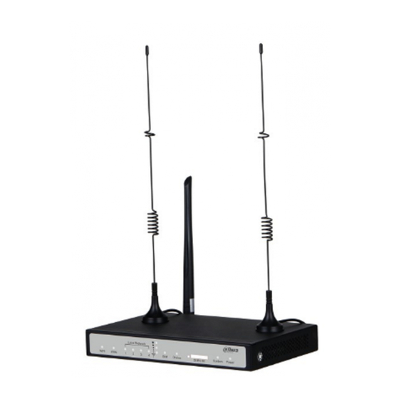
Introduction Overview DH-WM4700-O 4G Router (hereinafter referred to as "the Router") is a kind of cellular terminal device that provides data transmission by public cellular network. It adopts high-powered industrial 32-bit CPU and is embedded real time operating system. It provides one RS232 (or RS485/RS422), four Ethernet LAN, one Ethernet WAN and one Wi-Fi port for serial, Ethernet and Wi-Fi devices to achieve data transmission and routing. -
Page 8: Typical Application
User’s Manual High-performance Multiple WAN access methods, including static IP, DHCP, L2TP, PPTP, PPPOE and 2.5G/3G/4G Double link backup between cellular and WAN(PPPOE, ADSL) (optional) VPN client (PPTP, L2TP, OPENVPN, IPSEC and GRE) VPN server (PPTP, L2TP, OPENVPN, IPSEC and GRE) ... -
Page 9: Installation
User’s Manual Installation The Router must be installed correctly to make it work properly. Install the Router under the guidance of qualified engineers. Forbid to install the Router when powered. Out-of-Box Checking Check if there is obvious damage to the appearance of the Router. ... -
Page 10: Installation And Cable Connection
User’s Manual Figure 2-2 Top panel (unit: mm [inch]) Installation and Cable Connection 2.3.1 Antenna Installation The cellular antenna and the WIFI antenna cannot be connected reversely, otherwise the Router cannot work. Make sure that the antennas are tightened, or the signal quality will be affected. ... -
Page 11: Power Supply
User’s Manual Figure 2-3 SIM/UIM card installation 2.3.3 Power Supply The power supply range of the Router is 5V–36V DC. The standard power supply is 12V/1.5A When you use external power supply, make sure that the power supply is stable (that is, the ripple is less than 300mV, and the instantaneous voltage is not more than 36V) and the power is above 8W. -
Page 12: Reset
User’s Manual Indicator Status Description On: Network port is connected. On/Flash Local Network Flash: Data transmission is in progress. Network port is disconnected. On: WAN port is connected. On/Flash Flash: Data transmission is in progress. WAN port is disconnected. Wi-Fi is enabled. -
Page 13: Configuration And Management
Connect one end of the network cable to the Local Network (LAN) port of the Router, and another end of the network cable to the Ethernet port of the PC. Connect with Wi-Fi: The default SSID of the Router is "Dahua Wireless", and password is not required. Figure 3-1 Device connection Login Before you configure the Router, make sure that: ... -
Page 14: Setup
User’s Manual Figure 3-2 Initial interface Setup 3.3.1 Basic Setup You can configure WAN and network. 3.3.1.1 WAN Setup You can connect the Router to Internet by WAN setup. WAN Connection Type Step 1 Log in to the web interface of the Router. Step 2 In the left navigation menu, select Setup >... - Page 15 User’s Manual Figure 3-3 Set WAN connection type Table 3-1 Parameters to be configured when Static IP as the WAN connection type Parameter Description WAN IP Address Set IP address by your own or ISP assigns. Subnet Mask Set subnet mask by your own or ISP assigns. Gateway Set gateway by your own or ISP assigns Static DNS 1/DNS 2/DNS 3...
- Page 16 User’s Manual Table 3-2 Parameters when Automatic Configuration-DHCP as the WAN connection type Parameter Description Select online detection mode to detect whether the Internet connection is active. The following detection Keep Online Detection modes are available: None (disable this function), Ping, Route and TCP.
- Page 17 User’s Manual Table 3-4 Parameters to be configured when PPPoE as the WAN connection type Parameter Description User Name Enter the user name for login to the Internet. Password Enter the password for login to the Internet. Select online detection mode to detect whether the Internet connection is active.
- Page 18 User’s Manual Parameter Description Select online detection mode to detect whether the Internet connection is active. The following detection Keep Online Detection modes are available: None (disable this function), Ping, Route, PPP and TCP. Set time interval between two detections, expressed by Detection Interval seconds.
- Page 19 User’s Manual Figure 3-4 Optional settings Table 3-6 Parameter description of optional settings Parameter Description Router Name Set router name. The name length can be up to 39 characters. Host Name Enter host name and domain name which are provided by your ISP. Generally you can leave them blank.
- Page 20 User’s Manual Figure 3-5 Router IP Table 3-7 Parameter description of router IP Parameter Description Local IP Address Set local IP address of the Router. Subnet Mask Set the subnet mask of the Router. Set the internal gateway of the Router, the default internal gateway is the Gateway address of the Router.
- Page 21 User’s Manual Make sure that there is no other DHCP server in the network. Step 1 Log in to the web interface of the Router. Step 2 In the left navigation menu, select Setup > Basic Setup. Step 3 In Network Address Server Settings (DHCP) section, set parameters. Figure 3-7 DHCP setting Table 3-8 Description of DHCP parameters...
- Page 22 User’s Manual Parameter Description Specifies the lease period of the dynamic IP address occupied by a network user. After the dynamic IP address expires, a new dynamic IP address will be automatically assigned to the user. Client Lease Time The value range is 0–99999, and the default value is 1440 minutes (1 day).
-
Page 23: Dynamic Dns
User’s Manual Table 3-9 Parameter description of time settings Parameter Description NTP Client Whether to get the system time from NTP server or not. Time Zone Set time zone. Summer Time (DST) Set as needed. Enter IP address of NTP server, up to 32 characters. If blank, the Server IP/Name system will find a server by default. - Page 24 User’s Manual Figure 3-9 3322.org as DDNS service Step 4 Set DDNS parameters. Table 3-10 Description of DDNS parameters Parameter Description Enter the user name that is registered with the DDNS server. The User Name maximum length is 64 characters. Enter the password for the user name that is registered with the DDNS Password server.
-
Page 25: Mac Address Clone
User’s Manual 3.3.3 MAC Address Clone Some ISPs might require you to register your MAC address. If you do not want to re-register your MAC address, you can clone the MAC address of the Router to your MAC address registered with ISP. Step 1 Log in to the web interface of the Router. - Page 26 User’s Manual Step 3 In Operating Mode section, select an operating mode. The following operating modes are available: Gateway, BGP, RIP2 Router, OSPF Router and Router. The default operating mode is Gateway. And Gateway mode is also recommended for most users. The parameters might vary according to the different operating modes.
-
Page 27: Vlans
User’s Manual Parameter Description Destination Enter the address of the network or host to which you want to assign a static routing. The subnet mask determines which portion of an IP address is the network Subnet Mask portion, and which portion is the host portion. Enter the IP address of the gateway device that is between the router and Gateway the destination network or host. -
Page 28: Networking
User’s Manual Figure 3-12 VLAN Step 4 Click Save to save the configuration. Step 5 Click Apply Settings to apply the configuration. Step 6 (Optional) Click Cancel Changes to cancel the configuration. 3.3.6 Networking You can create bridges, assign ports to bridges, view the current bridging list, configure ports and manage DHCPD servers. - Page 29 User’s Manual Figure 3-13 Create bridge The smaller the number after the bridge, the higher the priority. For example, the priority of Bridge 0 is higher than that of Bridge 1. Click Delete, you can delete the corresponding bridge. ...
- Page 30 User’s Manual 3.3.6.2 Port Setup You can set the properties of each port. Take ra0 port as an example. Step 1 Log in to the web interface of the Router. Step 2 In the left navigation menu, select Setup > Networking. Step 3 In Port Setup section, select Unbridged next to Network Configuration ra0.
-
Page 31: Wireless
User’s Manual Step 3 In DHCPD section, click Add. Step 4 Configure DHCP. Select a port or a bridge in the first dropdown list. Set whether to enable DHCP in the second dropdown list. Start: Specify the start address. ... - Page 32 User’s Manual Figure 3-17 Configure wireless physical interface Table 3-13 Parameter description of physical interface Parameter Description The following wireless modes are available: AP, Client, Repeater, Repeater Wireless Mode Bridge. The following wireless network modes are available: Disabled: Disable wireless network. ...
-
Page 33: Wireless Security
User’s Manual Parameter Description Bridged: Bridge to the Router, normally select this option. Network Unbridged: No bridge to the Router, you need to manually configure Configuration IP address and subnet mask. Step 4 Click Save to save the configuration. Step 5 Click Apply Settings to apply the configuration. - Page 34 User’s Manual Figure 3-19 WPA2 Personal Security modes vary according to the Wireless Network Modes set in Wireless > Basic Settings. WPA algorithms vary according to different security modes. Table 3-14 Parameter description of security mode Parameter Description Authentication Type Select Open or Shared Key.
-
Page 35: Services
User’s Manual Parameter Description Radius Auth Sever The IP address of the RADIUS server that is connected to the Address Router. Radius Auth Server Port The RADIUS port (1812 by default). Radius Auth Shared The shared key between the RADIUS server and the Router. Secret Key Renewal Interva(in The range is 1–99999, and the default value is 3600. -
Page 36: Snmp
User’s Manual Step 1 Log in to the web interface of the Router. Step 2 In the left navigation menu, click Services . Step 3 In DNSMasq section, enable DNSMasq, and then set parameters. Figure 3-21 DNSMasq Table 3-15 Description of DNSMasq parameters Parameter Description Enables DHCP clients on the LAN to resolve static and dynamic DHCP... -
Page 37: System Log
User’s Manual Figure 3-22 Enable SNMP Table 3-16 Description of SNMP parameters Parameter Description Location Set the location identification of the device. Contact The contact information and name of SNMP. Name SNMP RO community name, the default is public, Only with read RO Community permission. -
Page 38: Telnet
User’s Manual 3.5.5 Telnet Telnet is a terminal emulation protocol that is commonly used on the Internet and TCP/IP-based networks. It allows end users or computers to log in to remote devices and run programs. You can enable a telnet server to connect to the Router with telnet. The username is admin and the password is the Router's password. - Page 39 User’s Manual Figure 3-23 Enable PPTP server Table 3-17 Description of PPTP server parameters Parameter Description Broadcast support Set whether to enable broadcast or not. Set whether to mandatorily enable MPPE (Microsoft Point-to-Point Force MPPE Encryption Encryption) encription of PPTP data. DNS1 DNS2 Set as needed.
- Page 40 User’s Manual Step 2 In the left navigation menu, select VPN > PPTP . Step 3 In PPTP Client section, enable PPTP Client, and set parameters. Figure 3-24 Enable PPTP client Table 3-18 Description of PPTP client parameters Parameter Description Server IP or DNS Name Enter IP address or DNS name of PPTP server.
-
Page 41: L2Tp
User’s Manual 3.6.2 L2TP 3.6.2.1 L2TP Server L2TP (Layer 2 Tunneling Protocol) is an industrial standard Internet tunneling protocol. It is similar to the PPTP protocol, and it can encrypt network data streams. The difference is that L2TP requires data-oriented and point-to-point connections, uses multiple tunnels and provides header compression, tunnel authentication. - Page 42 User’s Manual 3.6.2.2 L2TP Client Step 1 Log in to the web interface of the Router. Step 2 In the left navigation menu, select VPN > L2TP . Step 3 In L2TP Client section, enable L2TP Client, and set parameters. Figure 3-26 Enable L2TP client Table 3-20 Description of L2TP client parameters...
-
Page 43: Openvpn
User’s Manual Parameter Description Network Address Translation. Set whether to enable NAT. Fixed IP Set whether to enable fixed IP. It is disabled by default. Require CHAP Set whether to support CHAP. Refuse PAP Set whether to support PAP. Require Authentication Set whether to support authentication. - Page 44 User’s Manual Figure 3-27 Enable OPENVPN server Table 3-21 Description of OPENVPN server parameters Parameter Description WAN Up: Start after online. Start Type System: Start when bootup. Config via Support the following configuration modes: Server or Daemon. CA Cert Enter the public CA certificattion of server and client.
- Page 45 User’s Manual 3.6.3.2 OpenVPN Client Step 1 Log in to the web interface of the Router. Step 2 In the left navigation menu, select VPN > OPENVPN . Step 3 In OpenVPN Client section, enable Start OpenVPN Client, and set parameters. Figure 3-28 Enable OpenVPN client Table 3-22 Description of OPENVPN client parameters...
- Page 46 User’s Manual Parameter Description Public Client Cert Enter the public client certification. Private Client Key Enter the private client key. Figure 3-29 Advanced options Table 3-23 Description of advanced options Parameter Description TLS Cipher Select TLS encryption standard. None by default. Set whether to enable LZO compression during data Use LZO Compression transmission.
-
Page 47: Ipsec
User’s Manual Parameter Description Policy based Routing Customize the routing policy. PKCS12 Key Private key format, set as needed. Static Key Set as needed. Step 4 Click Save to save the configuration. Step 5 Click Apply Settings to apply the configuration. Step 6 (Optional) Click Cancel Changes to cancel the configuration. - Page 48 User’s Manual Figure 3-32 Connection type Name: Indicates the connection name, must be unique. Enabled: If enabled, the connection will send tunnel connection request when it is reboot or re-connection. Local WAN Interface: Local address of the tunnel. ...
- Page 49 User’s Manual Step 9 Click Apply Settings to save the configuration. Figure 3-33 Connection Status Table 3-25 Parameter description of connection status Parameter Description Connection number. Name The name of the IPSEC connection. Type Types and functions of the current IPSEC connection. Common Name Displays addresses and subnets of the local and peer.
- Page 50 User’s Manual Select Import A Cert in ADD Method. Figure 3-34 Import a certificate Set whether to include private key. Enter the name of the imported certificate and public CA certificate. Generate a certificate Select Generate A Cert in ADD Method. Figure 3-35 Generate a certificate Select a Signed Method.
-
Page 51: Gre
User’s Manual Figure 3-36 Certificate management Click to delete the certificate. Click to view the certificate details. Click to download the certificate. 3.6.5 GRE The GRE (Generic Routing Encapsulation) protocol encapsulates data packets of certain network layer protocols (such as IP and IPX) so that these encapsulated data packets can be transmitted in another network layer protocol (such as IP). -
Page 52: Security
User’s Manual Table 3-26 Description of GRE tunnel parameters Parameter Description Number Selectable tunnels. Up to 12 GRE tunnels can be set. Select Enable to enable the current GRE tunnel; select Disable to Status disable the current GRE tunnel. Name GRE tunnel name, the length can up to 30 charaters. - Page 53 User’s Manual Figure 3-38 Security Step 4 Configure Additional Filters. Filter Proxy: Using WAN proxy server may reduce the security of the gateway. Select the checkbox to deny any access to any WAN proxy server or deselect to disable the function. ...
-
Page 54: Log Management
User’s Manual Step 6 Configure Impede WAN DoS/Bruteforce. Limit SSH Access: This function limits SSH access requests from the WAN. For the same IP, up to 2 SSH connection requests are accepted per minute. Limit Telnet Access: This function restricts Telnet access requests from the WAN. For the same IP, up to 2 Telnet connection requests are accepted per minute. -
Page 55: Access Restrictions
User’s Manual Access Restrictions You can block or allow specific types of Internet applications, and set Internet access policies for specific PCs. 3.8.1 WAN Access Step 1 Log in to the web interface of the Router. Step 2 In the left navigation menu, select Access Restrictions > WAN Access . Step 3 Configure access policy. -
Page 56: Url Filter
User’s Manual The Router does not have a battery to keep the clock running. Turning off the Router power or rebooting the Router will cause the temporary failure of the Router clock. After the failure, if the NTP time server cannot be synchronized automatically, you need to recalibrate the time to ensure that the relevant functions controlled by time period perform correctly. -
Page 57: Packet Filter
User’s Manual In the left navigation menu, select Access Restrictions > MAC Filter . Step 2 Step 3 Enable MAC filter. Figure 3-42 MAC filter Step 4 Select a policy. Discard packets conform to the following rules: Only discard the matching ... - Page 58 User’s Manual Figure 3-43 Packet filter Step 4 Select a policy. Discard packets conform to the following rules: Only discard the matching packets in the list. Accept only the data packets conform to the following rules: Only accept the matching packets in the list.
-
Page 59: Nat
User’s Manual 3.9.1 Port Forwarding Port Forwarding allows you to set up public services on your network, such as web servers, ftp servers, e-mail servers, or other specialized Internet applications. Specialized Internet applications are any applications that use Internet access to perform functions, such as video conferencing or online gaming. -
Page 60: Dmz
User’s Manual to the specified computer. For security reasons, you may want to restrict port forwarding to only those ports that are in use. If you no longer use the port forwarding, it is recommended to cancel selection in the Enable checkbox to temporarily disable the port forwarding. If you only want to forward a single port, see "3.9.1 3.9.1Port Forwarding". -
Page 61: Virtual Ip Mapping
User’s Manual Figure 3-46 Step 4 Enter the IP Address of DMZ Host. Step 5 Click Save to save the configuration. Step 6 Click Apply Settings to apply the configuration. Step 7 (Optional) Click Cancel Changes to cancel the configuration. 3.9.4 Virtual IP Mapping Step 1 Log in to the web interface of the Router. -
Page 62: Classify
User’s Manual Step 3 Configure QoS settings. Figure 3-48 QoS settings Start QoS: Set whether to enable QoS. Port: Select port. Packet Scheduler: Select packet scheduler. Uplink (kbps): Set bandwidth for upload. It is generally 80% to 90% of your ... - Page 63 User’s Manual Step 1 Log in to the web interface of the Router. In the left navigation menu, select QoS Setting > Classify . Step 2 Step 3 Add netmasks and set netmask priorities. Step 4 Add MACs and set MAC priorities. Figure 3-50 Classify ...
-
Page 64: Serial Applications
User’s Manual For Bulk priority, the upload and download rates are both 1000 bit. The data streams with Bulk priority starts to be sent after the data streams with other priorities are sent. When there is only one level of data stream, the bandwidth of the data stream is limited only by the upload and download restrictions in QoS Settings. - Page 65 User’s Manual Table 3-29 Description of serial application parameters Parameter Description Indicates the number of bytes per second transmitted by the Router, Baudrate commonly used baud rate is 115200, 57600, 38400, 19200. The number of data bit can be 4, 5, 6, 7, 8, and usually in ASCII code. The Databit transmission starts from the lowest bit and is located by the clock.
-
Page 66: Administration
User’s Manual Step 6 (Optional) Click Cancel Changes to cancel the configuration. 3.12 Administration The network administrator can manage specific router functions to ensure access and security. 3.12.1 Router Management 3.12.1.1 Router Password Step 1 Log in to the web interface of the Router. Step 2 In the left navigation menu, select Administration >... - Page 67 User’s Manual Figure 3-53 Add user Step 4 Click Save to save the configuration. Step 5 Click Apply Settings to apply the configuration. Step 6 (Optional) Click Cancel Changes to cancel the configuration. 3.12.1.3 Web Access Step 1 Log in to the web interface of the Router. Step 2 In the left navigation menu, select Administration >...
- Page 68 User’s Manual Figure 3-55 Remote access Step 4 Click Save to save the configuration. Step 5 Click Apply Settings to apply the configuration. Step 6 (Optional) Click Cancel Changes to cancel the configuration. 3.12.1.5 Cron The Cron subsystem schedules execution of Linux commands. You will need to use the command line or startup scripts to use this function.
- Page 69 User’s Manual 3.12.1.7 Remote Management You can monitor, manage and configure the Router remotely through the custom remote management server. Step 1 Log in to the web interface of the Router. Step 2 In the left navigation menu, select Administration > Management . Step 3 In Remote Management section, enable remote management, and then set parameters as needed.
-
Page 70: Keep Alive
User’s Manual Step 7 (Optional) Click Cancel Changes to cancel the configuration. 3.12.2 Keep Alive You can schedule to turn on/off and reboot of the Router. Step 1 Log in to the web interface of the Router. Step 2 In the left navigation menu, select Administration > Keep Alive . Step 3 In Schedule Boot&Shutdown section, enable Schedule Boot&Shutdown. -
Page 71: Factory Defaults
User’s Manual Figure 3-61 Run commands Run Commands: You can run command lines through the web interface. In Commands text box, enter command and then click Run Commands. Save Startup: You can set command lines that are executed when the Router ... -
Page 72: Firmware Upgrade
User’s Manual After resetting, all configuration is restored to factory defaults. Step 5 (Optional) Click Cancel Changes to cancel the configuration. 3.12.5 Firmware Upgrade You can get the upgrading file from technical support, and upgrade the Router to a new firmware version. -
Page 73: Status
User’s Manual 3.13 Status 3.13.1 Router You can view system information, serial application status, memory and network of the Router. All information is read-only. Step 1 Log in to the web interface of the Router. Step 2 In the left navigation menu, select Status > Router . Figure 3-63 Router information... -
Page 74: Wan
User’s Manual Table 3-30 Description of router information Parameter Description System The name of the Router, you can modify it in Setup > Basic Setup. Router Name For details, refer to "3.3.1 Basic Setup." Router Model The model of the Router. Firmware Version The firmware version of the Router. - Page 75 User’s Manual Configuration Type: Display the information required by your ISP for connection to the Internet. You can modify the information in Setup > Basic Setup. For details, refer to "3.3.1 Basic Setup." Total Traffic: Display the Internet traffic of the Router since the latest reboot. ...
-
Page 76: Lan
User’s Manual Figure 3-65 Traffic 3.13.3 LAN You can view the LAN status, active clients, DHCP status and DHCP clients. Step 1 Log in to the web interface of the Router. Step 2 In the left navigation menu, select Status > LAN . - Page 77 User’s Manual Figure 3-66 Table 3-31 Description of LAN parameters Parameter Description LAN Status MAC Address MAC address of LAN. IP Address IP address of LAN. Subnet Mask Subnet mask of LAN. Gateway Gateway of LAN. Local DNS DNS of LAN. Active Clients Host Name Host name of LAN client.
-
Page 78: Wireless
User’s Manual Parameter Description When DNSMasq is disabled, the value is uDHCPd. Starting IP address of the DHCP server to start with when assigning Start IP Address IP addresses. Ending IP address of the DHCP server to end with when assigning IP End IP Address addresses. - Page 79 User’s Manual Figure 3-67 Wireless Table 3-32 Description of wireless parameters Parameter Description Wireless Status MAC Address MAC address of the wireless client. Radio Display whether radio is on or not. Mode Wireless mode. Network Wireless network mode. SSID Wireless network name. Channel Wireless network channel.
-
Page 80: Device Management
User’s Manual Parameter Description Interface Interface of wireless client. Uptime Connection duration of wireless client. TX Rate Transmission rate of wireless client. RX Rate Receiving rate of wireless client. Signal Signal of wireless client. Noise Noise of wireless client. Signal to noise ratio of wireless client. Signal Quality Signal quality of wireless client. -
Page 81: Bandwidth
User’s Manual 3.13.6 Bandwidth You can view the bandwidth of LAN, WAN and wireless network. Step 1 Log in to the web interface of the Router. Step 2 In the left navigation menu, select Status > Bandwidth . The abscissa axis of the graph indicates time. ... -
Page 82: System Information
User’s Manual Figure 3-69 Bandwidth 3.13.7 System Information You can view system information including the Router, wireless network, wireless packet, wireless clients, DHCP clients, services and memory. - Page 83 User’s Manual Step 1 Log in to the web interface of the Router. Step 2 In the left navigation menu, select Status > Sys-Info . Figure 3-70 System information Table 3-33 Description of system information parameters Parameter Description Router Router Name Name of the Router.
- Page 84 User’s Manual Parameter Description SSID Name of wireless network. Channel Channel of wireless network. TX Power Transmission power of wireless network. Rate Transmission rate of wireless network. Wireless Packet Info Received (RX) Received data packet. Transmitted (TX) Transmitted data packet. Wireless client MAC Address MAC address of wireless client.
-
Page 85: Appendix 1 Cybersecurity Recommendations
User’s Manual Appendix 1 Cybersecurity Recommendations Cybersecurity is more than just a buzzword: it’s something that pertains to every device that is connected to the internet. IP video surveillance is not immune to cyber risks, but taking basic steps toward protecting and strengthening networks and networked appliances will make them less susceptible to attacks. - Page 86 User’s Manual Change Default HTTP and Other Service Ports We suggest you to change default HTTP and other service ports into any set of numbers between 1024~65535, reducing the risk of outsiders being able to guess which ports you are using. Enable HTTPS We suggest you to enable HTTPS, so that you visit Web service through a secure communication channel.
- Page 87 User’s Manual The network should be partitioned and isolated according to the actual network needs. If there are no communication requirements between two sub networks, it is suggested to use VLAN, network GAP and other technologies to partition the network, so as to achieve the network isolation effect.
- Page 88 User’s Manual...
Need help?
Do you have a question about the DH-WM4700-O and is the answer not in the manual?
Questions and answers