Table of Contents
Advertisement
Advertisement
Table of Contents

Related Manuals for Reichert Manual Lensometer ML1


Summary of Contents for Reichert Manual Lensometer ML1
- Page 1 ® Manual Lensometer User’s Guide...
- Page 2 The information contained in this document was accurate at time of publication. Specifications subject to change without notice. Reichert, Inc. reserves the right to make changes in the product described in this manual without notice and without incorporating those changes in any products already sold.
-
Page 3: Table Of Contents
Table of Contents Table of Contents ..................... 3 Warnings and Cautions ................... 4 Symbol Information ..................6 Introduction ...................... 7 Indications for Use ..................7 Contraindications ..................7 Instrument Setup ..................... 8 Unpacking ....................8 Parts Diagram .................... 9 Battery Installation ................... 10 Tilt Angle .................... -
Page 4: Warnings And Cautions
Warnings and Cautions Reichert Technologies (Reichert) is not responsible for the safety and reliability of this instrument when: • Assembly, disassembly, repair, or modification is made by unauthorized dealers or persons. • Instrument is not used in accordance with this User’s Guide. WaRning: an inSTRUCTiOn THaT DRaWS aTTEnTiOn TO THE RiSK OF inJURY OR DEaTH. - Page 5 Warnings and Cautions (continued) WaRning: ALWAYS KEEP BATTERIES OUT OF THE REACH OF INFANTS AND YOUNG CHILDREN TO PREVENT THEM FROM BEING SWALLOWED. IF SWALLOWED, CONSULT A PHYSICIAN IMMEDIATELY. CaUTiOn: an inSTRUCTiOn THaT DRaWS aTTEnTiOn TO THE RiSK OF DaMagE TO THE PRODUCT. CaUTiOn: THE INTERNAL CIRCUITRY OF THE INSTRUMENT CONTAINS ELECTROSTATIC DISCHARGE SENSITIVE DEVICES (ESDS) THAT MAY BE SENSITIVE TO STATIC CHARGES PRODUCED BY THE HUMAN BODY.
-
Page 6: Symbol Information
Symbol Information The following symbols appear on the instrument. Consult Instructions for Use symbol indicating important operating and maintenance instructions that are included in this User’s Guide Caution Symbol indicating important information and maintenance instructions that are included in the User’s Guide Type B Product Classification Class I Equipment, Continuous Operation Protective Earth... -
Page 7: Introduction
We recommend that you read it carefully prior to use and follow the instructions in the guide to ensure optimum performance of your new instrument. Please retain this manual for future reference and to share with other users. Additional copies can be obtained from your authorized Reichert dealer or from the Reichert Customer Service department. Contact information is provided at the end of this guide. indications for Use The ML1 is a battery powered lensmeter that is intended for measuring spectacle lenses as well as contact lenses. -
Page 8: Instrument Setup
Instrument Setup (continued) Unpacking Cardboard Box User’s Open the top of the shipping box and remove the Styrofoam guide User’s Guide from the top. Refer to Figure SU-01. Remove the Styrofoam Box and set on a flat surface. Refer to Figure SU-02. Cut or remove the Tape that is at the seam of the Styrofoam Box. -
Page 9: Parts Diagram
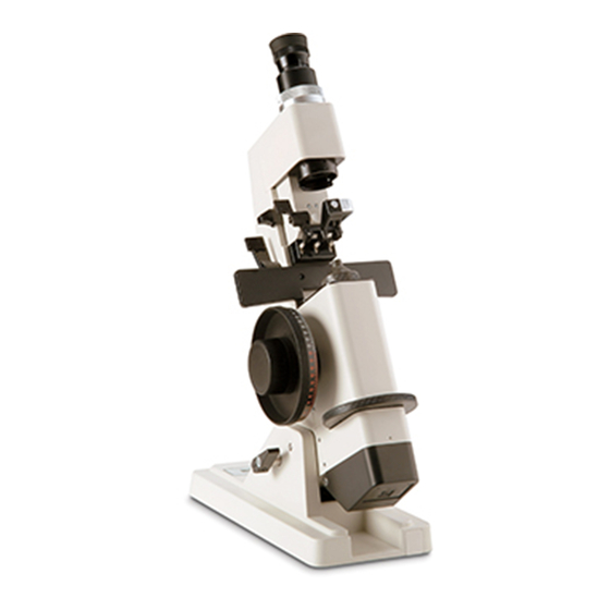
Instrument Setup (continued) Parts Diagram ML1 Parts On-Off Switch Table Lift Lever Lens Clamp Handle Marking Lever Focusable Eyepiece Prism Compensator Lens Clamp Lens Holder Power Wheel Axis Wheel Battery Compartment Tilt Lock Lever Lens Table Figure SU-05 ML1 Parts Diagram accessories 15110-016 ) Dust Cover (P/N... -
Page 10: Battery Installation
Instrument Setup (continued) Battery installation Screw Using a flathead screwdriver, remove the Screw that secures the Battery Compartment to the ML1. Refer to Figure SU-07. Open the Battery Compartment and install the two “AAA” Batteries. Refer to Figure SU-08. Close the Battery Compartment and secure it with the screw. -
Page 11: Focus The Eyepiece
Instrument Setup (continued) Focus the Eyepiece It is important to insure that the ML1 is focused before use. Each user must focus the instrument for their individual eye. Failure to focus the ML1 could result in note: inaccurate measurements. Place a white sheet of paper at the position of the Lens Holder. -
Page 12: Holding A Lens For Measurement
Instructions For Use Holding a Lens for Measurement Sphere Place the concave, or back side of the lens Lines against the Lens Holder. note: If the lens is edged, or “laid out” for cutting, place the 180° line parallel to the Lens Table. -
Page 13: Reading In Plus Cylinder
Instructions For Use (continued) Lens analysis Lens Centering and Marking (continued) The optical center of a lens can be located and Reading Plus Cylinder marked in the following manner. Set the Power Wheel at the lower of the two focusing positions (toward the minus end of With the lens clamped in position against the the scale). -
Page 14: Measuring Prism Power
Instructions For Use (continued) Measuring Prism Power Prism power is indicated by the position of the center of the target with respect to the Eyepiece reticle. The innermost Prism Ring is 1 prism diopter, the second Prism Ring is 2 prism diopters, and the third Prism Ring is 3 prism diopters. -
Page 15: Measuring Bifocal Additions
Instructions For Use (continued) Measuring Bifocal additions Lens Holder Removed The bifocal addition equals the difference between the powers measured through the distance and reading portion of a bifocal lens with the segment surface against the Lens Holder. Fused Bifocal Lens Place the front or convex surface of the lens against the Lens Holder. -
Page 16: Cleaning & Maintenance
Cleaning & Maintenance Cleaning Exterior Cleaning CaUTiOn: DO NOT USE SOLVENTS OR STRONG CLEANING SOLUTIONS ON ANY PART OF THIS INSTRUMENT AS DAMAGE TO THE UNIT MAY OCCUR. Clean the exterior surfaces with a soft cloth moistened with a mild soap solution (1 cc of Inkwell liquid dish soap to one liter of clean, filtered water Cover... -
Page 17: Target Centering
Cleaning & Maintenance (continued) Target Centering Screw Removing Prism Compensator It is best if the target centering is done without the Prism Compensator in place. Using a flathead screwdriver, remove the 3 Screws in the Prism Compensator. Refer to Figures MM-03 and MM-04. note: There is a Screw on the top of the Prism Compensator, and one on each side. -
Page 18: Troubleshooting
Troubleshooting Chart of Common Errors Problem Cause Solution Does not read “0” without a lens in Eyepiece not focused for user. Focus Eyepiece. place Needs calibration. Have instrument serviced. High powers off same amount in Vertex distance setting incorrect. Remove any pads. the same direction, i.e +12.00 reads Pads may be installed on the +12.25, -12.00 reads -11.75. -
Page 19: Specifications
Specifications Catalog number 15110 Physical Dimensions Size: Weight, unpacked: 11 lbs. ( 4.9 Kg) Height: 18.7 in. (47.5 cm) Width: 5.1 in. (12.9 cm) Depth: 12.9 in. (32.8 cm) Electrical Voltage: 3 VDC (2 AAA batteries at 1.5 VDC each) Vertex Power Prismatic Power Range... -
Page 20: Warranty
U.S. Patent, Reichert will defend such action at its expense and will pay costs and damages awarded in any such action, provided that Reichert shall have sole control of the defense of any such action with information and assistance (at Reichert’s expense) for such defense, and of all negotiation for the settlement and compromise thereof. - Page 21 Notes 15110-101 Rev. D...
- Page 22 Notes (continued) 15110-101 Rev. D...
- Page 23 Notes (continued) 15110-101 Rev. D...
- Page 24 15110-101 Rev. D January 21, 2013...
Need help?
Do you have a question about the Manual Lensometer ML1 and is the answer not in the manual?
Questions and answers