Advertisement
Quick Links
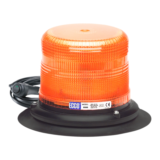
Models 6550 & 6570 Strobe Beacons
6500 Series strobe beacons are designed to meet SAE
J1318 Class II specifications. Available in 5" & 7" height
profiles, the 6500 Series feature a thread-on lens,
snap-fit flashtube, and 3 bolt flange/1" pipe or magnetic
mounting options. 6500 Series strobes will function
on 12-48 VDC electrical systems and offer a choice of
80FPM double flash or 65FPM quad flash operation.
!
WARNING!
Failure to install or use this product according to manufacturers recommendations may result in property
damage, serious bodily/personal injury, and/or death to you and those you are seeking to protect!
Do not install and/or operate this safety product unless you have read and understand the
safety information contained in this manual.
1. Proper installation combined with operator training in the use, care, and maintenance of emergency warning devices
are essential to ensure the safety of you and those you are seeking to protect.
2. Exercise caution when working with live electrical connections.
3. This product must be properly grounded. Inadequate grounding and/or shorting of electrical connections can cause
high current arcing, which can cause personal injury and/or severe vehicle damage, including fire.
4. Proper placement and installation are vital to the performance of this warning device. Install this product so that output
performance of the system is maximized and the controls are placed within convenient reach of the operator so that
s/he can operate the system without losing eye contact with the roadway.
5. It is the responsibility of the vehicle operator to ensure during use that all features of this product work correctly. In
use, the vehicle operator should ensure the projection of the warning signal is not blocked by vehicle components
(i.e., open trunks or compartment doors), people, vehicles, or other obstructions.
6. The use of this or any other warning device does not ensure all drivers can or will observe or react to a warning signal.
Never take the right-of-way for granted. It is your responsibility to be sure you can proceed safely before entering an
intersection, driving against traffic, responding at a high rate of speed, or walking on or around traffic lanes.
7. This equipment is intended for use by authorized personnel only. The user is responsible for understanding and
obeying all laws regarding warning signal devices. Therefore, the user should check all applicable city, state, and
federal laws and regulations. The manufacturer assumes no liability for any loss resulting from the use of this
warning device.
Specifications:
Size:
6550X - Permanent 6.8" dia. x 4.9" high
6550X-VM - V/Magnet 7.8" dia. x 5.6" high
6570X - Permanent 6.8" dia. x 6.7" high
6570X-VM - V/Magnet 7.8" dia. x 7.5" high
Weight:
6550X - Permanent approx. 1.2 lbs.
6550X-VM - V/Magnet approx. 2.7 lbs.
6570X - Permanent approx. 1.4 lbs.
6570X-VM - V/Magnet approx. 2.8 lbs.
920-6500-00 Rev. D
Installation and Operation Instructions
360° Strobe Beacon
Input Voltage:
12 to 48 VDC (9-56V)
Current Draw:
2.37 Amps - Peak
30.3 Watts - Maximum
Operating temperature range: -30 to +50ºC
Page 1 of 3
Advertisement

Related Manuals for Ecco 6500 Series


Summary of Contents for Ecco 6500 Series
- Page 1 Installation and Operation Instructions 360° Strobe Beacon Models 6550 & 6570 Strobe Beacons 6500 Series strobe beacons are designed to meet SAE J1318 Class II specifications. Available in 5” & 7” height profiles, the 6500 Series feature a thread-on lens, snap-fit flashtube, and 3 bolt flange/1”...
- Page 2 SWITCH BLACK (USER SUPPLIED) WHITE N/C = DOUBLE FLASH GROUND Pipe Mounting: The 6500 series base comes with 1” NPT threads for pipe GROUNDED = QUAD FLASH GROUND mounting. Temporary Mounting, Vacuum-Magnet Mount: The Vacuum-Magnet Figure 3 Mount feature includes a suction cup on the bottom of the beacon, with a magnet inside of the suction cup, for a secure, temporary mount.
- Page 3 Replacement Parts & Accessories: Description Part Number Flash Tube R6501FT Lens, 4” (replacement for 6550) R6050LX* Lens, 6” (replacement for 6570) R6070LX* Magnet Mount Kit A6600MK Self Leveling Bracket A6600SLB Branch Guard (for use with 6550) A6050BG Branch Guard (for use with 6570) A6070BG Dust Cover (for use with 6550) A6050DC...