Table of Contents
Advertisement
Quick Links
EN
KLEMANTIS
INSTRUCTION MANUAL
KLEMANTIS AS1000 (AL2001)
KLEMANTIS AS500 (AL2002)
Congratulations on choosing an ADB product! We thank you for your custom.
Please note that this xture - like all the others in the wide ADB range - has been designed and made with total
quality assurance to ensure excellent performance and best meet your expectations and requirements.
www.adbstagelight.com
Advertisement
Table of Contents

Related Manuals for ADB Stagelight KLEMANTIS AS1000

Summary of Contents for ADB Stagelight KLEMANTIS AS1000
- Page 1 KLEMANTIS INSTRUCTION MANUAL KLEMANTIS AS1000 (AL2001) KLEMANTIS AS500 (AL2002) Congratulations on choosing an ADB product! We thank you for your custom. Please note that this xture - like all the others in the wide ADB range - has been designed and made with total quality assurance to ensure excellent performance and best meet your expectations and requirements.
- Page 2 4.1.3 How to calculate positioning distance from cyclorama 4.1.4 Focus and tilt angle 4.1.5 Tips&tricks Connecting to main Supply Connecting the control signal line: DMX / Art-Net Control Panel MAINTENANCE Fuses replacing Periodic cleaning TECH DATA APPENDIX The Klemantis installation procedure KLEMANTIS AS1000 AS500...
-
Page 3: Safety Information
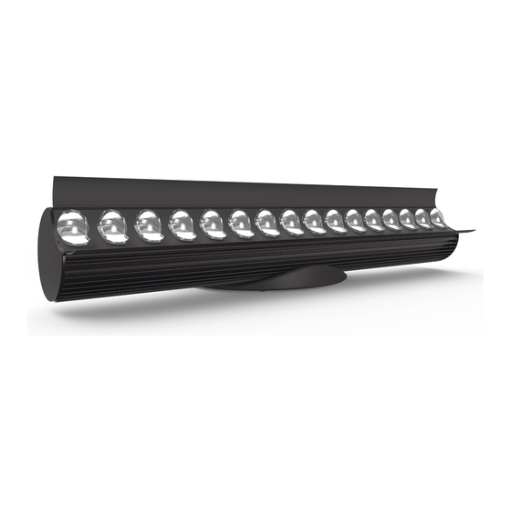
Ref: FIS01B - KLEMANTIS AS Safety Information Где достать ИНСТРУКЦИЮ ПО ТЕХНИКЕ БЕЗОПАСНОСТИ на нескольких языках. Вы всегда можете скачать многоязычную инструкцию по технике безопасности для данного изделия DB пo ссылке: www.adbstagelight.com/downloads Ref: FIS01B - KLEMANTIS AS Safety Information KLEMANTIS AS1000 AS500... - Page 4 The KLEMANTIS is available in two models, both designed to work in a linear array. The KLEMANTIS AS1000 is one metre long and fitted with 16 multi- source LED modules. The KLEMANTIS AS500 is half a metre long and features 8 LEDs. They can be used horizontally, vertically, laid on the floor, or hung from above on a bar.
-
Page 5: Product Overview
INTERNAL LIGHT COLLIMATION SYSTEM. AVOID INTENSE LIGHT FROM ANY ANGLE CONTIENT SYSTÈME DE COLLIMATION DE LUMIÈRE. SAFETY ROPE ATTACHMENT POINTS EVITER LUMIÈRE INTENSE DE N'IMPORTE QUEL ANGLE Fig. 1 Klemantis AS1000 components DMX IN POWER IN CONTROL PANEL USB PORT POWER OUT... -
Page 6: Package Contents
3. UNPACKING Package contents Package contents - Fig. 3 • 1x Safety Information Leaflet FIS01B • 1x Omega Bracket 319102-801 • 1x powerCON TRUE 1 to Bare Ends Mains Cable CAB02B-801 KLEMANTIS AS1000 AS500... -
Page 7: Optional Accessories
(provided in a box where both symmetrical and asymmetrical lenses can be stored) B - Hook clamp - ADB-1092.10.600 C - Safety bond - 105041/001 D - Junction pin - AA20000001020 E - Base accessory to mount 2 Klemantis - AR2001000000 KLEMANTIS AS1000 AS500... -
Page 8: Installation And Start-Up
The Klemantis has been designed to work in a linear set-up, so the fixtures must be aligned in a continuous row. The maximum clearance allowed between one fixture and the next is 20 mm. Klemantis installation Fig. 5 Top and bottom configuration KLEMANTIS AS1000 AS500... - Page 9 4000 3000 2000 1000 Y, mm -1000 -2000 -3000 -4000 -5000 -4000 -3000 -2000 -1000 1000 2000 3000 4000 5000 X, mm Figure 2 top and bottom row setup Fig. 6 Klemantis' performance with different installation configurations KLEMANTIS AS1000 AS500...
- Page 10 The safety cables must be fastened to the unit supporting structure and then hooked onto the fastening points found on the sides of the fixture. WARNING: light collimation system This unit contains an internal light collimation system. Avoid intense light from any angle. KLEMANTIS AS1000 AS500...
- Page 11 In the case of the two-row set-up, the recommended distance for the most even light on a cyclorama can be easily calculated using the following formula: d = distance from cyclorama H = height of cyclorama Klemantis Distance (D) KLEMANTIS AS1000 AS500...
- Page 12 • Tilting effect: if the Klemantis units on the same row are not tilted properly and equally, the light intensity varies on the cyclorama adjust Klemantis tilting. Should you require further instructions about installation, see Appendix: Klemantis Installation Steps. KLEMANTIS AS1000 AS500...
- Page 13 Up to five Klemantis AS1000s (or eight Klemantis AS500s) may be linked via Power Thru connectors on the same power line (16 Amp). NOTE: plug the cable into AC power 100/240V 50/60Hz on a non-dimmable circuit. Do not connect to a dimmer power line. KLEMANTIS AS1000 AS500...
-
Page 14: Connecting The Control Signal Line: Dmx / Art-Net
Use XLR type 5-pin male/female connectors for end connections. A terminating plug with a resistance of 120 (minimum 1/4 W) between terminals 2 and 3 must be inserted on the last unit. IMPORTANT: Avoid contact between wires and with the metal casing of the connector. The casing must be connected to the shield braid and pin 1. KLEMANTIS AS1000 AS500... -
Page 15: Control Panel
To activate this function press the UP and DOWN keys at the same time while the display is in standby. The condition is memorized and saved for subsequent switching too. To return to the initial state, repeat the operation again. KLEMANTIS AS1000 AS500... -
Page 16: Maintenance
5. MAINTENANCE Replacing fuses Two 6.3 x 32 mm 4AT fuses (p/n FUS00B) Replacing fuses - Fig. 16 Each fixture has two fuses on the main power cord connection. KLEMANTIS AS1000 AS500... -
Page 17: Routine Cleaning
IMPORTANT: Do not use compressed air at more than four atmospheres to clean the inside of the fixture (LED board area). Clean the lenses using water and neutral soap only. Then dry thoroughly with a soft, non-abrasive cloth. (CAUTION: the use of alcohol or other detergents could damage the lenses). KLEMANTIS AS1000 AS500... - Page 18 6. TECH DATA KLEMANTIS AS1000 - AS500 (7.56") (15.75") 1000 (10.67") (39.37") (15.75") (7.56") (10.67") (19.68") ELECTRICAL SPECS OPERATIONAL SPECS • Power supply: electronic auto-ranging • Working position: 45° std, rot. +/-45° • Input voltage range: 110-240Vac 50/60 Hz • Min. distance to illuminated surface: 0.2m •...
- Page 19 3. If the floor is not level, use the adjustable feet (fig. 18) 4. Adjust the tilt of each unit (a digital bubble level smartphone app may be used): a. Before tightening the clamps, set all the Klemantis units to 0° in the back-stage-to-front-stage direction (fig. 19). KLEMANTIS AS1000 AS500...
- Page 20 Set the tilt angle to 43.5° to the vertical (wall) or 46.5° to the horizontal (floor) (fig. 21-22). The correct reference angles are shown in the layout for completeness (fig. 23). 43.5° 46.5° 43.65° 45.00° 46.35° 45.00° KLEMANTIS AS1000 AS500...
- Page 21 13. For each Klemantis unit identified, an observer should stand in front of the cyclorama while another person tilts the Klemantis slightly (without a digital level) to adjust its tilt finely based on feedback from the observer. KLEMANTIS AS1000 AS500...
- Page 22 KLEMANTIS AS1000 AS500...
- Page 23 KLEMANTIS AS1000 AS500...
- Page 24 I - 24068 Seriate (BG) - via Pastrengo, 3/b Phone +39 035 654311 - www.adbstagelight.com...
Need help?
Do you have a question about the KLEMANTIS AS1000 and is the answer not in the manual?
Questions and answers