Table of Contents
Advertisement
Quick Links
Advertisement
Table of Contents
Troubleshooting

Related Manuals for H. Winter PLANERMAX 810

Summary of Contents for H. Winter PLANERMAX 810
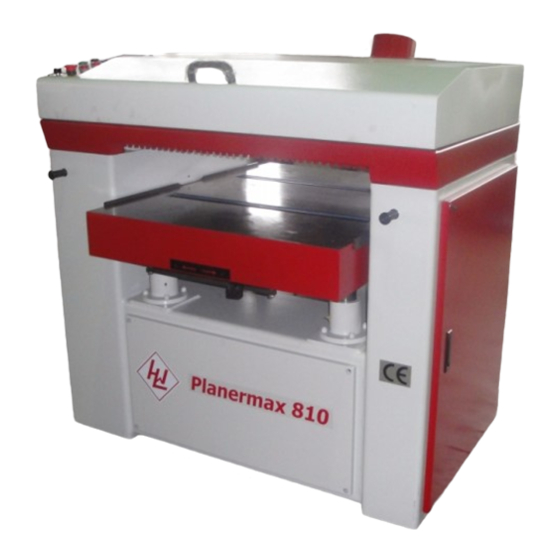
- Page 1 WINTER Thickness planner PLANERMAX 810 www.winter-holztechnik.de...
-
Page 2: Table Of Contents
Table of contents Warnings ..............................3 Using restriction............................4 Introduction ..............................5 Description..............................5 Specifications ..............................6 Unpacking ..............................7 Installation ..............................8 Electrical Connections..........................8 Adjustments and Controls ........................10 Changing Knives ............................12 Dust Collection............................14 Belt Tension & Replacement........................15 Changing Fuses ............................16 Maintenance .............................16 Troubleshooting: Operating Problems......................17 Troubleshooting: Mechanical & Electrical Problems ................18 Electric Specification ..........................19 Electric part list ............................20 APPENDIX - INVERTER (with inverter machines only).................27... -
Page 3: Warnings
Warnings Know your machine. For your own safety, read the operation manual carefully. Learn the machine applications and limitations, as well as specific potential hazards pertinent to this machine. Keep guards in place and in working order. If a guard must be removed for maintenance or cleaning, make sure it is properly reattached before using the machine again. -
Page 4: Using Restriction
of equal thickness behind it when feeding through the planer. Be sure the last board of a butted sequence is 250mm long or longer. 24. Wear ear protectors (plug or muffs) during extended periods of operation. If the board being planned stops feeding, disengage or turn the feed off and turn the power off. -
Page 5: Introduction
Introduction This manual is covering the safe operation and maintenance procedures for a Model An-926/932/940/952 Planer. This manual contains instructions on installation, Maintenance instructions, safety precautions, General operating procedures and parts breakdown. This machine has been designed and constructed to provide years of trouble free operation if used in accordance with instructions set forth in this manual. -
Page 6: Specifications
Specifications Model An-926 An-932 An-940 An-952 Main motor 7.5kw/11kw(opt) 15kw 18.7kw 22.5Kw Table elevation motor 0.187Kw 0.375Kw 0.375Kw 0.375Kw 1.5Kw 1.5Kw 1.5Kw Feed motor 0.75Kw Variable feed speed 6-18 6-18 6-18 6-18 (m/min.) Cutterhead speed 4500 4500 4500 4500 (RPM) Cutterhead diameter (mm) Knife size... -
Page 7: Unpacking
Unpacking Contents of the Shipping Container 1. Planer Open shipping crate and check for shipping 2. Open-end wrenches (11-13,17-19,mm) damage. Report any damage immediately to 3. Owner’s manual you distributor and shipping agent. Read 4. Air drive……………1set 5. Bits (T20) for TCT….5pce this instruction manual... -
Page 8: Installation
be connected. Place a warning placard on Installation the fuse holder or circuit breaker to prevent it being turned on while the machine is Tools required for installation being wired. Always follow proper Lock wrench set (provided) level Out/Tag Out procedures when performing forklift or crane with straps. - Page 9 the fuses or reset the breakers at the power source). 9. Test the rotation of the cutter head. Turn on the main power switch (see Figure 2) and then the main motor switch (figure 4). The pulley on the main motor (on the side near the motor) should rotate clockwise.
-
Page 10: Adjustments And Controls
the handle to set the feed speed. Speed ranges Adjustments and Controls from 6 to 18 m/min. Figure 3 shows the control panel for the planer. The Brake Release switch (Hood inside) frees Starting procedure the cutter head so that it can be moved by hand Turn Main Switch to position “︱”.﹝NOTE: The (e.g. - Page 11 of control unit Correcting Raise the table To raise the table press the up-arrow buttons or Before operating the planer, the control unit should “-“ on control. be check for accuracy and calibrated if necessary. To lower the table press the down-arrow buttons or “+“...
-
Page 12: Changing Knives
Table parallelism: For accurate planning, the table must be parallel with the cutterhead. Lack of parallelism results in a taper over the width of the workpiece. Use the knife gauge to ensure knives have the same protrusion along the length of the cutterhead. Maximum deviation allowed for good planning is 0.02mm. - Page 13 Check cutterhead insert size 14 x 14 x 2.0mm knife bevel should be slightly below the outside and angle 30° diameter of the cutterhead 4. Clean cutterhead & insert, set the insert in Press the knife with knife gage Lightly tighten two position, lubricate the M6 x 1.0 screw outside and center gib screws.
-
Page 14: Dust Collection
Dust Collection It is strongly recommended this planer be connected to a dust extraction system, via the 5”(125mm) dust port at the rear of the planer. Your dust collector should have at least 1500 CFM capacity. And The required air flow speed at the end of flexible hose is 30-34m/sec. -
Page 15: Belt Tension & Replacement
Belt Tension & Replacement Do not turn the sprockets on the 1. Note Belts should be replaced as a matched set table raising screws with the chain of four removed. Doing so will misalign the Pull out on the lever at the fore side of the table machine, and raise the hood 3. -
Page 16: Changing Fuses
Changing Fuses Maintenance Disconnect planer from power source, and open the electrical enclosure. Pull open the cover on a fuse holder. As shown in figure10 and slide out the old Before and intervention on the fuse. Replace it with a new one of the proper machine, disconnect it from the amperage. -
Page 17: Troubleshooting: Operating Problems
Troubleshooting: Operating Problems Trouble Probable cause Remedy Table rollers not set properly. Adjust rollers to proper height. Inadequate support of long Support long boards with extension rollers. Snipe(NOTE: boards. Snipe can be Uneven feed roller pressure Adjust feed roller tension. minimized but not front to back. -
Page 18: Troubleshooting: Mechanical & Electrical Problems
Troubleshooting: Mechanical & Electrical Problems Trouble Probable Cause Remedy Board Digital display calibrated Follow calibration procedures thickness does properly. not match digital display Chain jumping Inadequate chain tension. Adjust chain tension. Sprockets misaligned. Align sprockets. Sprockets worn. Replace sprockets. No incoming power. Verify unit is connected to power, and main switch is set to “|”. -
Page 19: Electric Specification
Electric Specification Mold AN-926 AN-932 AN-940 AN-952 Power 7.5kw 11kw 15kw 18kw 22kw Spindle Range 16-24A 24-32A 25-40A 40-63A 40-63A Motor Setting Electric cable cross-section 2.0mm 3.5mm 5.5mm 5.5mm electric cable cross-section Main 3.5mm 5.5mm 14mm Power 0.75Kw 1.5Kw 1.5Kw 1.5Kw Range 4-6.3A... -
Page 20: Electric Part List
Electric part list Yuan An Iron Works Co., Ltd. SCHEDULE ELECTRICAL Sheet No. 1 EQUIPMENT TYPE: An-926 Item Suppliers Designation and Function Technical data Supplier Remarks Designation Reference Ith= 16A Moeller T0-/E EN60947-3 Disconnection switch Ue=Ui=690V Fuse 25A/600V DF6-AB10 EN60269-1 Fuse 6A/600V DF6-AB10... - Page 21 Electrical Box UNIT SART STOP...
- Page 22 R1 S1 T1 R2 S2 T2 R3 S3 T3 0.3KV 110V 220V 31 FU7 U1 V1 W1 U2 V2 W2 1.5/0.75KW 0.375/0.187KW Feed Motor Elevation motor 7.5/11/15/18/22Kw SPINDLE...
- Page 23 KT1 KM1 Braker Elevation/Up Elevation/Down Line Infeed magnetic magnetic magnetic starter starter starter...
- Page 24 Part List Description Description Hex Cap Screw M8*25 Base Side cove Table Raising Sprocket Bearing 6204 Middle cover Hex Cap Screw M8*25 Hood Raising Lift Bearing house Dust Hood Assembly Nut M16 Key 6*6*20 Anti-Kickback Finger Raising chain Anti-Kickback Finger Spacer Raising Reducer Anti-Kickback Finger Axle Raising Motor...
- Page 25 Description Description Retaining ring R52 Bearing house LH Bearing 6205 Bearing Cover Outfeed house LH Bearing Nut Outfeed Frame LH Retaining ring S30 Outfeed Spring Retaining ring R62 Spring Screw Bearing 6206 Spring Nut Bearing House Press Bar Infeed Frame RH Outfeed houst RH Hex Cap Screw M10*35 100.
- Page 26 117. Sprocket Axle 118. Sprocket 119. Bearing 6203 120. Nut M8 121. Spring 122. Hex Cap Screw M8*25 and Nut 1 123. Hex Cap Screw M8*45and Nut 124. Hex Cap Screw M10*30 125. Washer 126. Ring 127. Motor Pulley 128. Motor 129.
-
Page 27: Appendix - Inverter (With Inverter Machines Only)
APPENDIX - INVERTER (with inverter machines only) A f r e q u e n c y i n v e r t e r i s b u i l t i n i n v e r t e r m a c h i n e s t o p r o v i d e v a r i a b l e s p e e d c o n t r o l f o r f e e d r o l l e r .
Need help?
Do you have a question about the PLANERMAX 810 and is the answer not in the manual?
Questions and answers