
Related Manuals for Technica CM 100 High

Summary of Contents for Technica CM 100 High
- Page 1 IVN2Eth Capture Module: CM 100 High USER MANUAL January 2020 Manual-Version: 0.991 Firmware: v009.005.060 Hardware: v1.1 up to v3.1...
-
Page 2: Table Of Contents
Control Panel tab ....................21 4.4.1 Restart target ....................22 4.4.2 Configuration ....................22 4.4.3 Prevent sleep ....................24 4.4.3.1 Staying alive conditions ............... 24 4.4.3.2 Wake up conditions ................24 4.4.4 WakeUp Lines and Actuator ............... 25 CM 100 High User Manual... - Page 3 APPLICATION AND FIRMWARE UPDATE ............... 47 Preconditions and important information ............47 Update via GB-A Port ..................48 Update via 100BASE-T1 Port on the frontside (power connector) ....49 ADDITIONAL INFORMATION ..................50 LIST OF FIGURES ....................... 51 CM 100 High User Manual...
- Page 4 CHANGELOG ......................52 CONTACT ........................53 CM 100 High User Manual...
-
Page 5: General Information
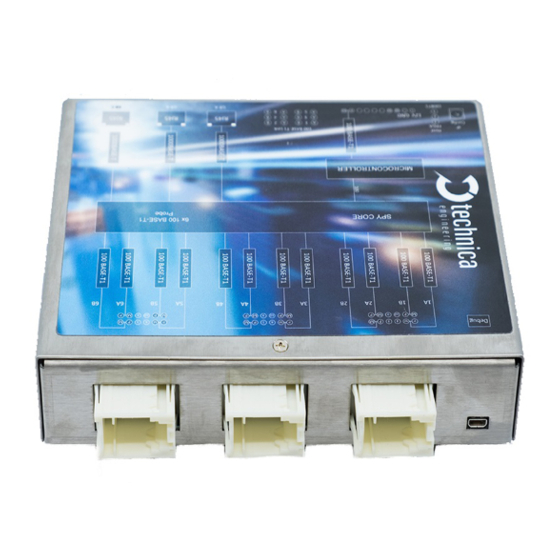
1.1 Functionality and Features of the CM_100_High Figure 1-1: Chapture_Module_100_High The Technica Engineering Capture_Module_100_High from Technica Engineering GmbH is used to capture the traffic from 1 x 1000BASE-T1 line (between two DUTs) and 2 x 100BASE-T1 lines, correspondingly. The traffic is captured without causing interference on the network and delivered with a 40 ns resolution hardware time stamp, thus making the analysis of AVB/TSN traffic possible. - Page 6 167 x 143 x 32 mm Weight: 1,0 kg International Protection: IP 2 0 Operating temperature: -30°Celsius to 50°Celsius (prototype) LINKS: The User can download the latest firmware and documentation for the CM_100_High here: https://technica-engineering.de/en/produkt/capture-module-100-high/ CM 100 High User Manual...
-
Page 7: Warranty And Safety Information
Do not place the device near to highly flammable materials due to fire danger. If you wish to discard a CM_CAN_Combo from Technica Engineering GmbH, please contact your dealer or supplier for further information. This symbol is only valid in the European Union. If you wish to discard this product, please contact your local authorities or dealer and ask for the correct method of disposal. -
Page 8: Declaration Of Conformity
Figure 1-3: Copy of Declaration of conformity 1.4 Scope of Delivery The delivery includes: 1x CM_100_High Cable-set can be ordered separately. 1x Cable-set o 1m Ethernet Cable, o connectors, o crimp contacts, o cables, o banana plugs CM 100 High User Manual... -
Page 9: Hardware Interfaces
2 HARDWARE INTERFACES 2.1 Connectors On the label on top of the device you can see an overview about all HW-Interfaces of the CM_100_High: Figure 2-1: Label of CM_100_High with pinning information CM 100 High User Manual... -
Page 10: Power Connector - Black Mqs Connector Frontside (10 Pins One Row)
Tyco, MQS Buchsengehäuse 10 Pol Black 1-929423-2 Tyco crimp contact 928999-1 Table 2-1: Parts of black MQS connector Note: You can use the official Tyco tool for these crimp contacts. A cheap variant is the crimp tool for “PSK” contacts. CM 100 High User Manual... -
Page 11: Rj45 Ethernet Connectors
There are three RJ45 Standard Ethernet connectors for Gigabit Ethernet on the front side (GB-A to GB-C). Here you can log and configure the device. And these ports are for time synchronization between different CaptureModules from Technica. For details please see 4.5.3. - Page 12 100 BASE-T1 4B Plus 100 BASE-T1 4A Minus n.c. n.c. n.c. n.c. 100 BASE-T1 3A Minus 100 BASE-T1 3B Plus 100 BASE-T1 3A Plus 100 BASE-T1 3B Minus Table 2-5: Pinning of Tyco MQS Connector middle CM 100 High User Manual...
-
Page 13: Micro Hdmi Connector
It is overtaken after 500ms by a software reset. The current IP-address is shown on the System Information tab. Access to the CM_100_High is given through the defined configuration port or 100BASE-T1 Port on the Frontside (Host). CM 100 High User Manual... -
Page 14: Rotary-Switch In Status E
FPGA is damaged and must be repaired LED 3: The “Host” LED can toggle at two different speeds: Slow toggle (approx. 1 sec) during normal operation Fast toggle (approx. 0.2 sec) if device is in Bootloader mode CM 100 High User Manual... - Page 15 In the middle (2): These LEDs show the status of the connected devices to each 100BASE-T1-Port (1A to 6B) LED “on” (static) indicates LinkUp LED blinking means communication on 100BASE-T1 Port CM 100 High User Manual...
-
Page 16: Access By Webserver
2. Enter the IP Address in your standard web browser. For details see 2.2.1 HAPTER 4.3. HAPTER Note: Firefox is the recommended browser. 3. The following website should appear. Figure 3-1: Home Screen CM_100_High CM 100 High User Manual... -
Page 17: Configuration Of The Cm_100_High
After the restart, all changes are applied. 4.2 Home Screen Figure 4-2: CM_100_High Home Screen With the first access to the website you will get displayed the home screen. Please select one of the tabs for further configuration. CM 100 High User Manual... -
Page 18: System Information Tab
If these registers are displayed as “FFFFFFFF”, this port/PHY is defect. Rotary Switch: The configuration of the Rotary switch is displayed here. Hardware version: The version of your Hardware is displayed here. MAX10 Version: The Current Version of the MAX10 Chip is displayed here. CM 100 High User Manual... - Page 19 The current configured IP-address of the 100BASE-T1 port on the Frontside is displayed here. HW-IP address: The current IP-address of the configuration port (RJ-45 Port) is displayed here. Serial number: The Serial number of the CM_100_High is displayed here. CM 100 High User Manual...
-
Page 20: Ip Addresses
This is the IP address you get access to the Webserver by the 100BASE-T1 port. This IP-address can be changed here. Please type the new IP- address in the field. After leaving the focus of this field or pressing “Enter” you can save the changes. CM 100 High User Manual... -
Page 21: Control Panel Tab
Switch. It is not configurable by Website except in Rotary-Switch status “E”. For more information please see 2.2.1. HAPTER 4.4 Control Panel tab On this panel tabulator you can import/export the configuration and make general settings of the configuration. Figure 4-5: Control Panel CM 100 High User Manual... -
Page 22: Restart Target
Figure 4-7: Handling of configuration files Change Configuration name: Here you can change the name of the configuration from “Default” to any other name. Spaces, numbers and +-_;:. are allowed. After saving the new name is applied. CM 100 High User Manual... - Page 23 Alternatively, you can copy the path of the configuration file int the field. Then press the button “Submit Query”. Apply the changes by saving the configuration: Default: This Button resets the CM_100_High to default configuration, but not to the default IP-addresses! CM 100 High User Manual...
-
Page 24: Prevent Sleep
If the device is in sleep mode, it can only be waked up by high level on the WakeUP 1 or WakeUP 2. Note: A power reset will not wake up the device from sleep mode if you wait less than 15 seconds. Only the WakeUP lines will wake it up immediately. CM 100 High User Manual... -
Page 25: Wakeup Lines And Actuator
WakeUp Line 1. (kind of loop through). But it provides only power if there is no input. WakeUp Line 2 Actuator: If this box is unchecked, this wakeup line is only input and wakes up the device when supplied. CM 100 High User Manual... -
Page 26: Wup Time To Low
Figure 4-12: Sleep Timeout Here you define the time in seconds, which has to go by with no communication on the supervised ports before the CM_100_High falls asleep. Reasonable values are between 15s and 300s. CM 100 High User Manual... -
Page 27: Date And Time
Note: It makes sense to set the time if there is no PTP bridge master connected to the Capture Module, to have a timestamp near the real time. Otherwise it will be the difference from 01.01.1970 00:00:00. CM 100 High User Manual... -
Page 28: Switch Status Tab
This is an overview of all ports. A blue bar indicates the linkup status on this port. If you select a port or any other part of the CM_100_High, it is shown by blue text of the selected part. CM 100 High User Manual... -
Page 29: Spy Multiplexer
Traffic Shaping is enabled. Now it is possible to set a maximum Traffic Bandwidth, the data is sent on the configured logging port. Traffic Shaping is deactivated, and no Traffic Bandwidth is configurable. The data will be sent as fast as possible. CM 100 High User Manual... -
Page 30: Keep Original Vlans In Header
Allowed values for Timeout [ms] are between 100ms and 65535ms. 4.5.1.7 Logging Ports for packetization Here you define, which port is using packetization. GB-A/B/C is using packetization GB-A/B/C is using no packetization Note: Only one port can use packetization at the same time. CM 100 High User Manual... -
Page 31: Delay For Logging
If the internal memory reaches the max threshold at any time, we stop sending any message. Note: If the event gets true stored data is send with maximum bandwidth, so please activate traffic shaping if needed (see 4.5.1.2). HAPTER CM 100 High User Manual... -
Page 32: Filters Table
Advance Filter. 4.5.1.10 Edit Basic Filter When you press the button Edit Table F 4-16) you can apply different filters for the IGURE captured data. 4-17 shows the user Interface. IGURE CM 100 High User Manual... - Page 33 MAC_SRC: Hexadecimal separated by colon e.g. 11:22:33:aa:bb:cc MAC_DST: Hexadecimal separated by colon e.g. 11:22:33:aa:bb:cc ETH_TYPE: 2 bytes e.g. 88F7 Action: only one action is available DROP: Each frame that matches the Filter Entry will not be mirrored to the logging port CM 100 High User Manual...
-
Page 34: Edit Advance Filter
Edit Advance Filter When you press the button Edit Advance Filter. 4-16) you can apply different IGURE advance filters for the captured data. 4-18 shows the user Interface: IGURE Figure 4-18: User interface advanced filter CM 100 High User Manual... - Page 35 If the original logged frame contains a VLAN (inner or outer) the corresponding box must be checked: OutVlan: The original logged frame has outerVLAN-tag OutVlan: The original logged frame has no outerVLAN-tag InVlan: The original logged frame has innerVLAN-tag InVlan: The original logged frame has no innerVLAN-tag CM 100 High User Manual...
- Page 36 Subtype AVTP [1 bye]: XX[hex] Stream ID AVTP [8 bytes]: XXXXXXXXXXXXXXXX[hex] Value: Here you define the value of your Field. Allowed values depend on the chosen Field. How to use Advance Filter: Please see 4.7. HAPTER CM 100 High User Manual...
-
Page 37: Host Port
Keep Awake Reason Bus: This port is supervised. If on this port is communication, CM_100_High can’t go asleep. This port is not supervised. The Capture Module can fall asleep even there is communication on this port. CM 100 High User Manual... -
Page 38: Ports
A is also Config-port if no port is configured as Config-port. You don’t get access to the Webserver of the Capture Module by this port. The status messages of the Capture Module are not transmitted on this port. CM 100 High User Manual... - Page 39 PLP for the reply of the device connected to the 100BASE-T1 port (ARP-Target filter and IPv4 Destination filter). Please, activate the function Working as DLT-port, too. For further information please see 4.8. HAPTER CM 100 High User Manual...
-
Page 40: 100Base-T1 Ports
GB-A: GB-A is defined as logging port => logging with this port is possible. GB-B: GB-B is defined as logging port => logging with this port is possible. GB-C: GB-C is defined as logging port => logging with this port is possible. Keep Awake Reason Bus: CM 100 High User Manual... - Page 41 100BASE-T1-device Messages Received: Counter for received messages on this port from the connected 100BASE-T1-device Messages with Error: Counter for received messages on this port from the connected 100BASE-T1-device containing an error. For example, CRC errors. CM 100 High User Manual...
-
Page 42: Synchronisation Of Several Devices By Ptp (802.1As)
These packets are decoded, and the relevant information extracted. The extracted information is used later to generate, together with the information extracted from the propagation delay algorithm, the new corrected Sync and Follow Up messages that will CM 100 High User Manual... -
Page 43: Propagation Delay Measurement
The measures of the propagation delay are performed by each attached link of an 802.1as communication, it means each side of the link will generate and response to these packets, called: • Pdelay_Request, • Pdelay_Response and CM 100 High User Manual... -
Page 44: How To Setup A Synchronized Network With Capturemodules
Example for dropping a frame with outerVLAN (0x123) and IP-destination address 160.48.199.125 on one port Figure 4-24: Example Advance Filter Drop This rule drops frames with outerVLAN ID 0x123 and the destination IP address 160.48.199.125 on Port BR1B. CM 100 High User Manual... -
Page 45: Inject
The GB-A-Port is configured as follows: The important point here is the field IP for Injection. Here must be the IP-Address of the injecting device. Also Working as DLT-port must be activated. Figure 4-26: Example for IP Injection CM 100 High User Manual... - Page 46 4.5.1.11): HAPTER For this example, the filter looks like this: The Filter must remove the PLP-header, if the used protocol is bidirectional like for example TCP. Figure 4-28: Filter of our example for IP Injection CM 100 High User Manual...
-
Page 47: Application And Firmware Update
Please follow this update instruction to avoid erroneous states of the device. Technica Engineering may charge support fees for repair service. Only upgrade to the latest firmware. And always bootloader and application Firewall must be deactivated, or Port 69 and Port 9000 must be open You need a stable 12 Volt DC power supply. -
Page 48: Update Via Gb-A Port
8. Do a power reset 9. Check the Host-LED if blinking in normal mode. 10. YES => Please check the version on webserver the System Information tab by browser NO => redo from point 4. ➔ Finished CM 100 High User Manual... -
Page 49: Update Via 100Base-T1 Port On The Frontside (Power Connector)
6. Wait until “Press any key…“ appears in cmd-window. 7. Press any key 8. Do a power reset 9. Check the Host-LED if blinking in normal mode. 10. YES => check webserver by browser NO => redo from point 5. ➔ Finished CM 100 High User Manual... -
Page 50: Additional Information
6 ADDITIONAL INFORMATION • The CM_100_High is optimized for automotive use. The maximum cable length for 100BASE-T1 segments is limited to 15 meters. • Hardware v2.4 requires at least firmware v003.001.020. CM 100 High User Manual... -
Page 51: List Of Figures
Figure 4-27: Example for IP Injection ................46 Figure 4-28: Filter of our example for IP Injection ............46 Figure 5-1: Update on GB-Port ..................48 Figure 5-2: left side update with MediaConverter, right side update with MediaGateway ............................49 CM 100 High User Manual... - Page 52 8 CHANGELOG Version Chapter Description Date 0.98 Draft Version 24.07.2019 CM 100 High User Manual...
- Page 53 If you have any questions regarding this product, please feel free to contact us: Technica Engineering GmbH Leopoldstr. 236 80807 München Germany Technical support: support@technica-engineering.de General information: Info@technica-engineering.de Most current user manuals and product information: https://technica-engineering.de/ CM 100 High User Manual...
- Page 54 CM 100 High User Manual...
Need help?
Do you have a question about the CM 100 High and is the answer not in the manual?
Questions and answers