Advertisement
PTM-ETR
echoflex
Powered by ETC
Wireless Switches
Installation Guide
This guide covers all Echoflex switch models.
The Echoflex switch models include:
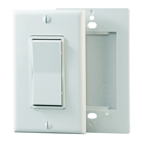
PTM265n* Single Decorator style wireless switch
PTM265Dn* Dual Decorator style wireless switch
ETRS1n# Single Resonate Wave style switch
ETRS2n# Dual Resonate Wave style switch
ETRH1nW Single Resonate Handheld switch
ETRH2nW Dual Resonate Handheld switch
PTM265KCAnW Keycard Activated switch
The character n is replaced with U for 902MHz, Y for 868MHz, C for 315MHz and
J for 928 MHz radios. The character * is replaced with W for white, B for black, A
for almond, V for ivory and R for brown; # available in W - white or B - black only
The package includes the switch and installation guide. Note - cover plates for
Decorator style switches are not included (can be ordered separately); Resonate
Wave switches include double sided tape.
Advertisement
Table of Contents

Related Manuals for echoflex PTM-ETR


Summary of Contents for echoflex PTM-ETR
- Page 1 PTM-ETR echoflex Powered by ETC Wireless Switches Installation Guide This guide covers all Echoflex switch models. The Echoflex switch models include: PTM265n* Single Decorator style wireless switch PTM265Dn* Dual Decorator style wireless switch ETRS1n# Single Resonate Wave style switch ETRS2n# Dual Resonate Wave style switch...
- Page 2 Product Overview The wireless switches communicate with controllers to activate the controllers internal relay. In most applications, the controller’s relay is connected to a lighting load or circuit and the wireless switch functions as a basic light switch. The switches requires no wiring connections and use no batteries. The kinetic energy of a finger press with the ON or OFF side of the switch generates enough energy to transmit the switch event.
- Page 3 3. Reinstall the faceplate assembly. DO NOT OVER TIGHTEN THE SCREWS. 4. Test operation of the switch by inserting a card and extracting. There should be an audible click with each insertion and extraction. Linking a Switch to a Controller The linking process requires the controller or receiver to be mounted, powered and within range of the switch to be linked.
- Page 4 Contain PTM 210J which complies with the Japanese radio law and is certified according to ARIB STD-T108 Copyright 2013-2016 Echoflex Solutions, Inc. | Specifications subject to change without notice. Document #8DC-5303 | Revision 2.6 | 8188M21-5303-1 | Rev E Echoflex Solutions, Inc.
Need help?
Do you have a question about the PTM-ETR and is the answer not in the manual?
Questions and answers