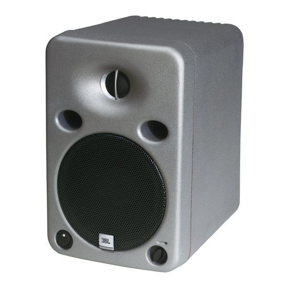
Summary of Contents for JBL LSR25P
- Page 1 Linear Spatial Reference LSR25P Studio Monitor System Preliminary Owner’s Manual...
- Page 2 When replacing a fuse, make sure to replace with only the correct type and fuse rating. 1. Read Instructions – Before operating your new JBL LSR product, please read all safety and operating instructions. 2. Keep these instructions – For future reference and troubleshooting purposes, retain these instructions.
- Page 3 The information contained in this document is confidential and the copyright of JBL Professional. To convey its contents, in part or in whole to any third party without prior written authorization is a violation of the...
-
Page 4: Table Of Contents
Table of Contents 1.0 Introduction ........................1 2.0 Getting Started ......................2 2.1 Unpacking ....................2 2.2 Placement ....................2 2.3 Audio Connections ..................2 2.4 AC Power Connections ................3 2.5 Making Sound Happen ................3 3.0 General Operation......................4 3.1 Audio Connections ..................4 3.2 AC Power Connections ................4 3.3 Audio Level Adjustment................5 3.4 High Frequency Adjustments ..............5 3.5 80 Hz High Pass Filtering ................6... -
Page 6: Introduction
LSR products have been based on fundamental research into all aspects of monitor design. JBL designed the entire system starting with the materials and topologies of the individual transducers, through to the final assembly of the diecast parts. The results are incredibly accurate reference systems with high dynamic capabilities and astonishingly low distortion. -
Page 7: Getting Started
The design of the LSR systems lend themselves to a wide variety of placement options. Covered here is a typical stereo setup for near to mid field monitoring. A deeper discussion of multi-channel sound setup is available from JBL in Tech Note Volume 3, Number 3. -
Page 8: Ac Power Connections
LSR25P monitors. Reduce the level of the monitor outputs of your console or preamp and also turn the volume on the front of the LSR25P monitors fully counter clock- wise for minimum gain. You can now turn on the monitors. There is a small delay with the turn on to accommodate for clicks and thumps from upstream equipment. -
Page 9: General Operation
The LSR25P will accept voltages from 100-120 or 200-240 Volts, 50-60 Hz when the voltage setting and fuse is correct. The ground terminal of the IEC plug is required by wiring codes and regulations. -
Page 10: Audio Level Adjustment
9 dB of attenuation in the 12 o’clock position. 3.4 High Frequency Adjustments: A group of four DIP switches are located in a recess on the back of the LSR25P. These allow the user to adjust various aspects of the frequency response. Switch 3 boosts the high frequency response by 1.5 dB above 2.3 kHz when moved into the up position. -
Page 11: 80 Hz High Pass Filtering
Switch 1 selects the 80 Hz setting when in the up position. 3.6 Workstation Boundary Compensation: The bass and low mid frequency response of the LSR25P can be adjusted to com- pensate when the system is located near a wall or other boundary surface. - Page 12 Section 3: General Operation...
-
Page 13: Specifications
Section 4: Specifications System: LSR25P Frequency Response (+1, -2 dB): 70 Hz - 20 kHz Enclosure Resonance Frequency: 55 Hz Low Frequency Extension: User controls set to default -3 dB: 65 Hz -6 dB: 56 Hz -10 dB: 48 Hz Low - High Frequency Crossover: 2.3 kHz... -
Page 14: Transducer Specifications
For this rea- son, any current JBL product may differ in some respect from its published description, but will always equal or exceed the original design specifications... -
Page 15: Performance Graphs
-100 -200 -300 -400 -500 -600 -700 -800 -900 -1000 1000 10000 Frequency 96 dB/1 m (Distortion raised 20 dB) o ess o a 2nd Harmonic 3rd Harmonic Frequency 1000 10000 LSR25P Response Curves Frequency 1000 10000... - Page 16 Section 4: Specifications...
-
Page 17: Appendix A: Wiring Recommendations
When using balanced sources with the LSR25P, it is recommended to use the XLR input on the LSR25P. This maintains a balanced signal and is the best way to reduce the possibility of hum or other interference For balanced sources, the HOT (+) signal from your source should be connected to Pin 2 of the XLR input as shown in Diagram A. - Page 18 XLR input of the LSR25P. Diagram D shows an unbalanced source connected to the bal- anced XLR input of the LSR monitor using twisted pair cable. Note that the shield is con- nected to the GROUND/SHIELD connector at the LSR input, but not at the source.
- Page 19 Appendix A: Wiring Recommendations Diagram D Unbalanced Source LSR XLR Input Pin 2 Pin 3 Sleeve Pin 1 Diagram E Unbalanced Source LSR XLR Input Pin 2 Pin 3 Sleeve Pin 1...
- Page 21 JBL Professional 8500 Balboa Boulevard, P.O. Box 2200 Northridge, California 91329 U.S.A. LSR25P MANUAL www.jblpro.com 98100056-00 CRP 1M A Harman International Company 11/99...


Need help?
Do you have a question about the LSR25P and is the answer not in the manual?
Questions and answers