Advertisement
Quick Links
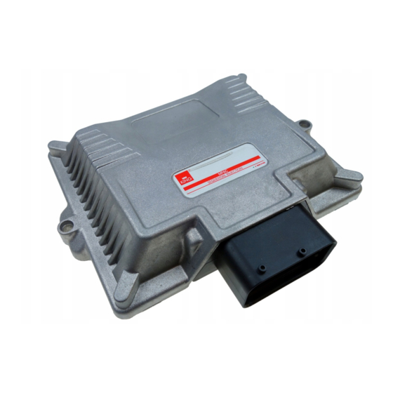
MP6C
6 CYL. INJECTION CONTROL UNIT OBD
INSTALLATION MANUAL
Specifiche tecniche / Technical specifications
Tensione di alimentazione / Supply voltage
Temperatura di funzionamento / Operating temperature
Fusibile di protezione / Protection fuse
Assorbimento di corrente con attuatori disattivi / Current absorption
with the actuators disabled
Assorbimento di corrente in modalità standby / Current absorption
in standby mode
Attuatori gestiti / Actuators managed
Uscita fili elettrovalvole gas / Wire output gas solenoid valves
Vbatt=10÷16V
-40÷110°C
MAX 15A
Imax ≤0.5A
Istandby ≤10 µA
Fino a 6 iniettori con caratteristiche:
Imax= 6A, Vbat max= 16V
up to 6 injectors with the following characteristics:
Imax=6A, Vbat max=16V
Pmax=25W, Imax=2A (potenza e corrente mas-
sima per ogni uscita con due uscite attive)
-----------------------------------------------------
Pmax=50W, Imax=4A (potenza e corrente mas-
sima con solo una uscita attiva)
Pmax=25W, Imax=2A (power and maximum
current for each output with two outputs enabled)
-----------------------------------------------------
Pmax=50W, Imax=4A (power and maximum
current with just one output enabled)
AVVERTENZE GENERALI/GENERAL INFORMATION
Dove fissare la Centralina /
- LONTANO da possibili INFILTRAZIONI D'ACQUA.
- FAR from any WATER LEAKAGE
- LONTANO da ECCESSIVE FONTI DI CALORE (esempio collettori di scarico).
- FAR from EXCESSIVE HEAT SOURCES (such as exhaust manifolds).
- LONTANO dai CAVI DELL'ALTA TENSIONE.
- FAR from HIGH-VOLTAGE CABLES.
Fare delle buone connessioni elettriche evitando l'uso dei "RUBACORRENTE".
Si tenga presente che la migliore connessione elettrica è la saldatura debitamente
isolata.
Create efficient electrical connections without using any "POWER TAPS".
Properly insulated soldering is the most effective type of electrical connection.
Avvisare il cliente che in caso di rottura del fusibile dell'impianto a GAS, il Sistema ripri-
stina i collegamenti dei dispostivi a cui è collegato. Si sconsiglia
vivamente di sostituire il fusibile con un'altro di amperaggio maggiore, cio' puo' provo-
care danni irreparabili.
Advise the customer that if the GAS system fuse burns, the connections of the devices to
which it is connected will be restored. It is strongly recommended not to replace the fuse
with another one with a higher amperage rating since it may cause irreparable damage.
Non aprire per nessun motivo la scatola della Centralina soprattutto con il motore in
moto o il quadro inserito, onde evitare danni irreparabili.
Si declina ogni responsabilità per danni a cose e persone derivati dalla manomissione
del proprio dispositivo da parte di personale non autorizzato con la conseguente perdita
di GARANZIA.
Do not open the Control Unit box for any reason, especially when the engine is running or the key
is in the ignition, to avoid irreparable damage.
Will not be held responsible for damage to property or injuries to persons if unauthorised
L'architettura dal sistema prevede l'utilizzo di un Relay esterno. Se non presente sul cablaggio
o in caso di sostituzione utilizzarne uno con le seguenti caratteristiche: 12V, 30A, contatto N.A.
The architecture of the system includes the use of an external relay. If not present in the wiring or
in the case of replacement use one with the following features: 12V, 30A, N.A. contact.
2-14
Where to install the control unit:
616000184 Rev. 111114-1
Advertisement

Subscribe to Our Youtube Channel
Related Manuals for AEB MP6C

Summary of Contents for AEB MP6C
- Page 1 Dove fissare la Centralina / - LONTANO da possibili INFILTRAZIONI D’ACQUA. - FAR from any WATER LEAKAGE MP6C - LONTANO da ECCESSIVE FONTI DI CALORE (esempio collettori di scarico). - FAR from EXCESSIVE HEAT SOURCES (such as exhaust manifolds). 6 CYL. INJECTION CONTROL UNIT OBD - LONTANO dai CAVI DELL’ALTA TENSIONE.
- Page 2 SCHEMA DI MONTAGGIO PT GAS MAP/ ASSEMBLY PT GAS MAP DIAGRAM COME FISSARE LA CENTRALINA / HOW TO INSTALL THE CONTROL UNIT PRESSIONE COLLETTORI (MAP) INSTALLAZIONE INSTALLAZIONE INSTALLAZIONE PRESSURE ERRATA ERRATA CORRETTA MANIFOLD (MAP) INCORRECT INCORRECT CORRECT INSTALLATION INSTALLATION INSTALLATION RIDUTTORE tyco PRESSURE...
- Page 3 CONNETTORE CENTRALINA GAS tyco PRESA PER INTERFACCIA SERIALE OPZIONALE VIOLA SONDA SENSORI LAMBDA 1 STANDARD A.E.B. GRIGIO MASSA OPZIONALE COLLEGAMENTO VIOLA/NERO GIRI MOTORE SONDA LAMBDA 2 BIANCO GRIGIO/NERO MARRONE VERDE SENSORI STANDARD BIANCO A.E.B. TIPO 1050 MASSA SENSORE DI PRESSIONE, BIANCO TEMPERATURA GAS E MAP VERDE...
- Page 4 GAS CONTROLLER CONNECTOR tyco SERIAL INTERFACE SOCKET OPTIONAL VIOLET OXYGEN A.E.B. STANDARD SENSOR 1 SENSORS GRAY OPTIONAL VIOLET/BLACK ENGINE RPM OXYGEN REFERENCE SENSOR 2 WHITE GRAY/BLACK BROWN GREEN A.E.B. STANDARD WHITE SENSORS TYPE 1050 GAS PRESSURE, TEMPERATURE WHITE GREEN AND MAP SENSOR GAS INLET LEVEL DO NOT LINK GREEN WIRE...
- Page 5 CONNECTION OF THE CUT INJECTOR WIRING COLLEGAMENTO DEL CABLAGGIO STACCA INIETTORI Come verificare il corretto collegamento del cablaggio stacca iniettori How to check the correct connection of the cut injector wiring Per verificare l’ottimale collegamento del cablaggio stacca iniettori occorre verificare prima di tutto, To check the correct connection of the cut injector wiring, you must first check, on the petrol injector sul connettore dell’iniettore benzina, su quale PIN arriva il positivo degli iniettori.
- Page 6 DESCRIZIONE DEI COLLEGAMENTI ALLA PRESA OBD DESCRIPTION OF THE CONNECTIONS MADE ON THE OBD CONNECTOR Through connection to the vehicle’s OBD socket, this new generation of GAS control units makes it possible to Questa Nuova Generazione di centraline GAS, attraverso la connessione alla presa OBD della vettura, permette acquire information useful for properly setting up the vehicle.
- Page 7 FUNZIONAMENTO DEL COMMUTATORE CHANGEOVER SWITCH OPERATION Descrizione del funzionamento Operating description Il commutatore che viene fornito nel kit dispone di un pulsante, 7 led luminosi e un cicalino inter The changeover switch supplied with the kit has one button, 7 LEDs and an internal buzzer. 4 GREEN LEDS - FUEL RED LED –...
Need help?
Do you have a question about the MP6C and is the answer not in the manual?
Questions and answers