
Related Manuals for MSC Technologies Avnet COM Express CXC-BT

Summary of Contents for MSC Technologies Avnet COM Express CXC-BT
- Page 1 User Manual COM Express Compact Module MSC CXC-BT Type 2 Pin-out Intel® Atom Series SOC Rev. 1.8 2020-06-12...
-
Page 2: Copyright Notice
All used product names, logos or trademarks are property of their respective owners. Certification MSC Technologies GmbH is certified according to DIN EN ISO 9001:2015 standards. Life-Cycle-Management MSC products are developed and manufactured according to high quality standards. Our life- cycle-management assures long term availability through permanent product maintenance. -
Page 3: Table Of Contents
MSC CXC-BT User Manual CONTENT Copyright Notice ..........................2 Important Information ........................2 Disclaimer ............................2 EMC Rules ............................2 Trademarks ............................2 Certification ............................2 Life-Cycle-Management ........................2 Product Support ..........................2 General Information ......................... 5 Revision History ........................5 Reference Documents....................... - Page 4 MSC CXC-BT User Manual 2.10.16 SPI Interface ........................30 2.10.17 Module Type Definition ......................31 2.10.18 Power and GND ........................32 2.11 Pin List for MSC CXC-BT module (Type 2) ................33 Jumpers and Connectors ........................35 Jumpers ...........................35 Fan Connector .........................35 Watchdog ............................36 System resources ...........................37 PCI IRQ Routing ........................37 SMB Address Map ........................38 BIOS ...............................38...
-
Page 5: General Information
MSC CXC-BT User Manual Bios Update from EFI Shell ......................72 Bios Update from Linux ......................72 Bios Update from Windows ......................72 Blind Restoration of Bios default settings (no display available) ..........72 Bios Recovery ..........................73 Bios Recovery (for BIOS version older than V1.50 )..............73 Clear CMOS and Recovery Jumper ..................74 Post Codes ..........................74 Technotes ............................75... -
Page 6: Reference Documents
MSC CXC-BT User Manual 1.2 Reference Documents COM Express Module Base Specification COM Express Revision 2.1 Last update: April 10 , 2012 PCI Local Bus Specification Rev. 2.1 PCI21.PDF Last update: June 1 , 1995 http://www.pcisig.com ATA/ATAPI-6 Specification d1410r3b.pdf http://www.t13.org/ Serial ATA Specification Serial ATA 1.0 gold.pdf Last update: August 29... -
Page 7: Introduction
MSC CXC-BT User Manual 1.3 Introduction COM Express™, an open specification of the PICMG (PCI Industrial Computer Manufacturer Group), is a module concept to bring PCI Express and other latest technologies like SATA, USB 2.0 and LVDS on a COM (Computer On Module). A COM Express™... -
Page 8: Module Photos
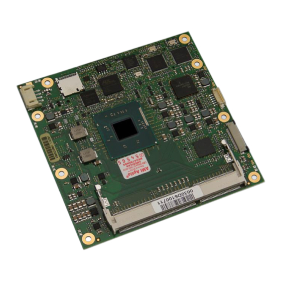
MSC CXC-BT User Manual 1.4 Module Photos Top side memory socket MAC address label BIOS label System On Chip (SOC) Layout revision Board Identification number (BID) Fan connector Micro SD card socket Top Side View ® COM Express connector Bottom side memory socket Bottom Side View 8 / 84... -
Page 9: Technical Description
MSC CXC-BT User Manual TECHNICAL DESCRIPTION 2.1 Key features The MSC CXC-BT COM Express module is designed as a type 2 module according to COM Express® Module Base Specification Revision 2.1. Key features include: Module size: 95 mm x 95 mm ... -
Page 10: Block Diagram
MSC CXC-BT User Manual 2.2 Block diagram 10 / 84... -
Page 11: Com Express Implementation
MSC CXC-BT User Manual 2.3 COM Express implementation COM Express™ required and optional features for pin-out type 2 are summarized in the following table. The features identified as Minimum (Min.) shall be implemented by all modules. Features identified up to Maximum (Max) may be additionally implemented by a module. The column MSC CXC-BT shows the features implemented by the MSC module. - Page 12 MSC CXC-BT User Manual Power Management A-B Thermal Protection 0 / 1 A-B Battery Low Alarm 0 / 1 A-B Suspend 0 / 1 A-B Wake 0 / 2 A-B Power Button Support 1 / 1 A-B Power Good 1 / 1 A-B VCC_5V_SBY Contacts 4 / 4 A-B Sleep Input...
-
Page 13: Functional Units
MSC CXC-BT User Manual 2.4 Functional units CPUs Intel® Atom Processor E3845, 1.91 GHz, Quad Core, 2MB L2, TDP 10W, (FCBGA 1170 Intel® HD Graphics. package) Intel® Atom Processor E3827, 1.75 GHz, Dual Core, TDP 8W, 1MB L2, Intel® HD Graphics. Intel®... - Page 14 MSC CXC-BT User Manual Ethernet 10/100/1000Base-TX (Intel® Ethernet Controller I210-AT). Sound Interface High Definition Audio Interface. Support for up to two external codec. Watchdog Timer Embedded controller creates watchdog alert and system reset. TPM (option) Optional TPM module, TPM 1.2, SLB9660. Fan Supply 4-pin header for support of a 12V PWM fan.
-
Page 15: Power Supply
MSC CXC-BT User Manual 2.5 Power Supply +12V primary power supply input +5V standby Option, is not required for module operation. If not present, customer must ensure that the supply voltages which are generated on the carrier board are switched off during suspend states, so that no current from the carrier board’s signal lines can flow to the CPU board. -
Page 16: System Memory
MSC CXC-BT User Manual 4. System is shut down into “Suspend to RAM” (S3) by Windows 7 Professional 64-bit SP1 with Wake On LAN enabled. S4 / S5 Input Power Module / CPU enabled enabled CXC-BT-001 (Intel® Atom 0.45 W 0.53 W 0.36 W 0.44 W... -
Page 17: Mechanical Dimensions
MSC CXC-BT User Manual 2.8 Mechanical Dimensions 2.8.1 Compact module There are two height options defined in the COM Express specification: 5mm and 8mm. The height option is defined by the connectors on the baseboard. 17 / 84... -
Page 18: Thermal Specifications
MSC CXC-BT User Manual 2.9 Thermal specifications The cooling solution of a COM Express module is based on a heat-spreader concept. A heat-spreader is a metal plate (typically aluminum) mounted on the top of the module. The connection between this plate and the module components is typically done by thermal interface materials like phase change foils, gap pads and copper or aluminum blocks. -
Page 19: Cpu Temperature Range
MSC CXC-BT User Manual 2.9.2 CPU Temperature Range in °C JUNCTION Intel® Atom E3805 - 40 to 110 Intel® Atom E3815 - 40 to 110 Intel® Atom E3825 - 40 to 110 Intel® Atom E3826 - 40 to 110 Intel® Atom E3827 - 40 to 110 Intel®... -
Page 20: Signal Description
MSC CXC-BT User Manual 2.10 Signal description Pins are listed in the following tables with the power rail associated with that pin, and for input and I/O pins, with the input voltage tolerance. The pin power rail and the pin input voltage tolerance may be different. An additional label, “Sus”, indicates that the pin is active during suspend states (S3, S4, S5). -
Page 21: Ethernet
MSC CXC-BT User Manual 2.10.2 Ethernet Signal Signal Power Remark / PU/PD/SR Description Source / Target Type Level Rail Tolerance GBE0_MDI[0:3]+ Analog 3.3V Sus 3.3V Gigabit Ethernet Controller 0: Media Dependent Interface Differential Intel® I210-AT GBE0_MDI[0:3]- Pairs 0,1,2,3. The MDI can operate in 1000, 100 and 10 Mbit / sec modes. -
Page 22: Serial Ata
MSC CXC-BT User Manual Signal Signal Power Remark / PU/PD/SR Description Source / Target Type Level Rail Tolerance 5.0V / 8mA eSR = 23.2 Ω Reset output to IDE device, active low. IDE_RESET# 3.3V JM330 5.0V / 8mA eSR = 75 Ω IDE_IRQ 3.3V Interrupt request from IDE device. - Page 23 MSC CXC-BT User Manual Signal Signal Power Remark / PU/PD/SR Description Source / Target Type Level Rail Tolerance ePU = 8.2 KΩ PCI bus Initiator Ready control line, active low. PCI_IRDY# CMOS 3,3V XIO2001 ePU = 8.2 KΩ PCI bus Target Ready control line, active low. PCI_TRDY# CMOS 3,3V XIO2001...
-
Page 24: Pci Express Lanes
MSC CXC-BT User Manual 2.10.6 PCI Express Lanes Signal Signal Power Remark / PU/PD/SR Description Source / Target Type Level Rail Tolerance PCIE_TX[0:1]+ PCIe 1.0V AC coupled PCI Express Differential Transmit Pairs 0 through 1 BT SOC lane 0, PCIE_TX[0:1]- on module BT SOC lane 1 or PCIe switch... -
Page 25: Usb
MSC CXC-BT User Manual 2.10.8 Signal Signal Power Remark / PU/PD/SR Description Source / Target Type Level Rail Tolerance USB[0:3]+ 3.3V Sus 3.3V USB differential pairs, channels 0 through 3 BT SOC USB[0:3]- Note: default enabled as EHCI in BIOS USB[4:7]+ 3.3V Sus 3.3V USB differential pairs, channels 4 through 7... -
Page 26: Lpc Bus
MSC CXC-BT User Manual 2.10.9 LPC Bus Signal Signal Power Rail Remark / PU/PD/SR Description Source / Target Type Level Tolerance LPC_AD[0:3] CMOS 3.3V 3.3V LPC multiplexed address, command and data bus BT SOC LPC_FRAME# CMOS 3.3V LPC frame indicates the start of an LPC cycle BT SOC LPC serial DMA request not connected LPC_DRQ0#... -
Page 27: Analog Vga
MSC CXC-BT User Manual 2.10.11 Analog VGA Signal Signal Power Remark / PU/PD/SR Description Source / Target Type Level Rail Tolerance ePD = 150 Ω VGA_RED Analog Red for monitor. Analog DAC output, designed to drive a 37.5-Ohm BT SOC equivalent load. -
Page 28: Power And System Management
MSC CXC-BT User Manual 2.10.13 Power and System Management Signal Signal Power Remark / PU/PD/SR Description Source / Target Type Level Rail Tolerance ePU = 10 KΩ PWRBTN# CMOS 3.3V Sus Power button to bring system out of or into Suspend states. Embedded Controller ePU = 10 KΩ... -
Page 29: General Purpose I/O
MSC CXC-BT User Manual Signal Signal Power Remark / PU/PD/SR Description Source / Target Type Level Rail Tolerance ePU = 2.2 KΩ SMB_CK CMOS 3.3V Sus 3.3V System Management Bus bidirectional clock line. Power sourced BT SOC, through 3.3V standby rail. It is not recommended to use this bus for Embedded customer devices. -
Page 30: Spi Interface
MSC CXC-BT User Manual Signal Signal Power Remark / PU/PD/SR Description Source / Type Level Rail Tolerance Target CMOS 1.8V/3.3V 1.8V / 3.3V iPU = 20 KΩ SDIO_CMD SDIO Command/Response. This signal is used for card initialization BT SOC ( GPO1 ) and for command transfers. -
Page 31: Module Type Definition
MSC CXC-BT User Manual 2.10.17 Module Type Definition Signal Signal Power Remark / PU/PD/SR Description Source / Target Type Level Rail Tolerance TYPE[0:2]# Type 2 module The TYPE pins indicate to the Carrier Board the Pin-out Type that is Carrier board logic implemented on the module. -
Page 32: Power And Gnd
MSC CXC-BT User Manual 2.10.18 Power and GND Signal Signal Power Remark / PU/PD/SR Description Source / Target Type Level Rail Tolerance VCC_12V Power 12V (±5%) Primary power input: +12V (±5%) Voltage Regulators VCC_5V_SBY Power 5V (±5%) Standby power input: +5.0V (±5%) VCC3.3V SUS If VCC5_SBY is used, all available VCC_5V_SBY pins on the regulator... -
Page 33: Pin List For Msc Cxc-Bt Module (Type 2)
MSC CXC-BT User Manual 2.11 Pin List for MSC CXC-BT module (Type 2) GND (FIXED) GND (FIXED) GND (FIXED) GND (FIXED) GBE0_MDI3- GBE0_ACT# IDE_D7 IDE_D5 GBE0_MDI3+ LPC_FRAME# IDE_D6 IDE_D10 GBE0_LINK100# LPC_AD0 IDE_D3 IDE_D11 GBE0_LINK1000# LPC_AD1 IDE_D15 IDE_D12 GBE0_MDI2- LPC_AD2 IDE_D8 IDE_D4 GBE0_MDI2+ LPC_AD3... - Page 34 MSC CXC-BT User Manual PCIE_TX1- PCIE_RX1- PEG_RX4+ (DDI1) PEG_TX4+ WAKE0# PEG_RX4- (DDI1) PEG_TX4- GPI2 WAKE1# RSVD PCIE_TX0+ PCIE_RX0+ PEG_RX5+ PEG_TX5+ PCIE_TX0- PCIE_RX0- PEG_RX5- PEG_TX5- GND (FIXED) GND (FIXED) GND (FIXED) GND (FIXED) LVDS_A0+ LVDS_B0+ PEG_RX6+ PEG_TX6+ LVDS_A0- LVDS_B0- PEG_RX6- PEG_TX6- LVDS_A1+ LVDS_B1+ CRTLDATA (DDI1)
-
Page 35: Jumpers And Connectors
MSC CXC-BT User Manual JUMPERS AND CONNECTORS 3.1 Jumpers There are four jumpers available on the module: RTC Reset:By shorting the pins of this jumper, the RTC Clock is reset and the values of the CMOS NV-RAM are cleared. This jumper is only functional in systems with battery at RTC power supply. -
Page 36: Watchdog
MSC CXC-BT User Manual TACHO Input for the tacho signal from the fan (open collector); two pulses / rotation PWM output signal for fan speed control. Caution! Using the power supply wide input range at more than +12V can damage the fan. The correct function of the fan is not guaranteed below +12V. -
Page 37: System Resources
MSC CXC-BT User Manual SYSTEM RESOURCES 5.1 PCI IRQ Routing HW-option without PCIe switch (Chipset PCIe lane 1 is connected directly to COMExpress connector): Interrupts of Controller Slot Number Dev / (or Onboard Device) Func PCIe Slot #1 0 / all PCIe Slot #2 0 / all PCI Slot #1 (IDSEL = AD20) -
Page 38: Smb Address Map
MSC CXC-BT User Manual 5.2 SMB Address Map Device Address * ANX1122 50h / 28h ANX1122 8Ch / 46h SO-DIMM 0 SPD EEPROM A0h / 50h SO-DIMM 1 SPD EEPROM A2h / 51h A8h / 54h CMOS Backup EEPROM AAh / 55h Embedded Controller C0h / 60h PLX PCIe switch... -
Page 39: Configuring The System Bios
MSC CXC-BT User Manual 6.1.4 Configuring the System BIOS To start the AMI Aptio Setup utility, press [ESC or DEL] to launch Setup. The setup main menu appears. The BIOS Menu Structure The BIOS Menu is structured in the following way: Main MSC Board Info Hardware Monitoring Measurement... - Page 40 MSC CXC-BT User Manual The Menu Bar The Menu Bar at the top of the window lists these selections: Menu Items Description Main Use this menu for basic system information. Advanced Use this menu to set the Advanced Features available on your system’s chipset.
-
Page 41: The Main Menu
MSC CXC-BT User Manual Display a submenu To display a submenu, use the arrow keys to move the cursor to the sub menu you want. Then press Enter. A pointer marks all submenus. 6.2 The Main Menu You can make the following selections on the Main Menu itself. Use the sub menus for other selections. -
Page 42: Msc Board Info
MSC CXC-BT User Manual 6.2.1 MSC Board Info Feature Options Description Manufacturer MSC Technologies GmbH Board Name Informative Shows the board name Board Revision Informative Shows the board revision Bios Version Informative Shows the bios version Serial Number Informative Shows the boards serial number... -
Page 43: Hardware Monitoring Measurement
MSC CXC-BT User Manual 6.2.2 Hardware Monitoring Measurement Feature Options Description CPU Temperature Informative Shows CPU Temperature Also supported in EAPI Note: CPU temperature is measured close to the CPU and does not reflect CPU die temperature System Temperature Informative Shows the current system temperature Memory Temperature Informative... -
Page 44: The Advanced Menu
MSC CXC-BT User Manual 6.3 The Advanced Menu Feature Options Description Trusted Computing Submenu Trusted Computing ( TPM ) ACPI Settings Submenu System ACPI Parameters Serial Port Console Submenu Serial Port Console Redirection Redirection CPU Configuration Submenu CPU Configuration Parameters PPM Configuration Submenu CPU PPM Configuration settings... -
Page 45: Trusted Computing ( Tpm 1.2)
MSC CXC-BT User Manual 6.3.1 Trusted Computing ( TPM 1.2) Feature Options Description TPM state Enabled Turn TPM Enable/Disable. NOTE: Disabled Your Computer will reboot during restart in order to change State of TPM. Pending Operation None Schedule an operation for the Security Enable take ownership Device. -
Page 46: Serial Port Console Redirection
MSC CXC-BT User Manual Feature Options Description Lock Legacy Resources Enabled Set to enabled to prevent the OS from Disabled reconfiguring the resources of the SIO device through ACPI. 6.3.4 Serial Port Console Redirection Feature Options Description Com 0 Console Enabled, Console Redirection Enable or Disable Redirection... -
Page 47: Cpu Configuration
MSC CXC-BT User Manual Feature Options Description Parity None, Even, Odd, Mark, A parity bit can be sent with the data Space bits to detect some transmission errors. Even: parity bit is 0 if the number of 1's in the data bits is even. Odd: parity bit is 0 if number of 1's in the data bits is odd. - Page 48 MSC CXC-BT User Manual Feature Options Description Disabled malicious buffer overflow attacks when combined with a supporting OS ® Intel Virtualization Enabled When enabled, a VMM can utilize the Technology Disabled additional hardware capabilities provided by Vanderpool Technology For more information see also technotes in Chapter 8.
-
Page 49: Ppm Configuration
MSC CXC-BT User Manual 6.3.7 PPM Configuration Feature Options Description ® EIST Enabled Enable or disable Intel Speedstep Disabled For more information see also technotes in Chapter 8. CPU C state report Enabled Enable/Disable CPU C state report to Disabled Max CPU C-state This option controls Max C state that the processor will support... -
Page 50: Internal Devices Configuration
MSC CXC-BT User Manual 6.3.9 Internal Devices Configuration Feature Options Description LPSS & SCC Devices PCI Mode, ACPI Mode LPSS & SCC Devices Mode Settings Mode Note : Use PCI Mode for Windows7 Use ACPI Mode for Windows 8 and above. -
Page 51: Csm Configuration
MSC CXC-BT User Manual Feature Options Description PXE boot wait time 1-5s Wait time to press ESC key to abort the PXE boot Media detect count 1-50 Number of times presence of media will be checked 6.3.12 CSM Configuration Feature Options Description CSM Support... -
Page 52: Nvme
MSC CXC-BT User Manual Feature Options Description Launch Video OPROM Do not launch, Controls the execution of UEFI and Legacy Video UEFI only, OPROM. Legacy only Legacy first UEFI first Other PCI device ROM UEFI Oprom For PCI devices other than Network, Mass storage Legacy Oprom or Video defines which Oprom to launch 6.3.13 NVMe... -
Page 53: Security Configuration
MSC CXC-BT User Manual Feature Options Description XHCI Hand-off Enabled, Disabled This is a workaround for OSes without XHCI hand-off support. The XHCI ownership change should be claimed by XHCI driver. EHCI Hand-off Enabled, Disabled This is a workaround for OSes without EHCI hand-off support. -
Page 54: Sio Wb627/Smsc 311X Configuration
MSC CXC-BT User Manual Feature Options Description TXE HMRFPO Enabled Enable or disable TXE Host ME Region Flash Disabled Protection Override TXE Firmware Update Enabled Enable or disable the possibility of runtime updates Disabled for the TXE firmware. TXE EOP Message Enabled Send EOP message before enter OS Disabled... -
Page 55: Ec Hardware Monitoring
MSC CXC-BT User Manual Options Description Feature COM B Setting: Auto, Resource setting for COM A on Winbond SIO I/O 2F8h, IRQ 3 I/O 3F8h, IRQ 3, 4, 5, 6, 7 ,10, 11, 12 I/O 2F8h, IRQ 3, 4, 5, 6, 7 ,8,10, 11, 12 I/O 3E8h, IRQ 3, 4, 5, 6, 7 ,10,... - Page 56 MSC CXC-BT User Manual By CPU sensor Disabled, Enabled Fan is auto controlled by CPU. Note: Please note that the CPU sensor is an external sensor placed near the CPU, and is not within the die itself. Fan Speed Off, 25%, 50%, 75%, Setup the fan duty cycle for manual fan 100% control.
- Page 57 MSC CXC-BT User Manual In temperature based mode up to three different sources can be selected: CPU temperature, board temperature sensor and system temperature sensor. Temperature based mode controls fan within 4 temperature zones and fixed PWM duty cycles. PWMmin 25% PWMmid 50% PWMmax 100% The temperature zones can be selected by temperature limits (T1, T2, T3).
-
Page 58: Legacy Irq Reservation
MSC CXC-BT User Manual 6.3.19 Legacy IRQ Reservation Feature Options Description Reserve IRQ 1,3,4,5,6,7,10,1 Reserve IRQ 1,12 Reserve IRQ 1,3,4,5,6,7,10,1 Reserve IRQ 1,12 Reserve IRQ 1,3,4,5,6,7,10,1 Reserve IRQ 1,12 Reserve IRQ 1,3,4,5,6,7,10,1 Reserve IRQ 1,12 6.3.20 Module-specific Initialization Feature Options Description User I2C Support GPIO-based,... -
Page 59: I210 Gigabit Connection Settings
MSC CXC-BT User Manual Feature Options Description POST Watchdog Enabled, Enable a watchdog during bios POST (before OS Disabled boot). ATTENTION: if this watchdog is configured with timeouts that are too agressive, the board might not be able to boot anymore! Note: Values are valid not until before second boot. -
Page 60: Flat Panel Configuration
MSC CXC-BT User Manual 6.4.1 Flat Panel Configuration Feature Options Description eDP Color Depth 18bit, 24bit eDP color depth selection. Adjust this according to the connected eDP display. When using LVDS, keep this setting consistent with the selected LVDS Mapping color depth. NOTE: This setting is only valid if legacy video bios is active! LVDS Panel Type... -
Page 61: North Bridge
MSC CXC-BT User Manual Feature Options Description PWM Polarity Active Low, Backlight PWM signal polarity Active High PWM Brightness 0-100% Select the initial brightness value of the flat panel PWM Frequency 200Hz, 1KHz, Select backlight PWM frequency for brightness 10KHz, 18KHz control 6.4.2 North Bridge Feature... -
Page 62: South Bridge
MSC CXC-BT User Manual Feature Options Description IGD Turbo Mode Enabled Enable: IGD Turbo enabled Disabled Disable: IGD Turbo disabled Primary Display Select which of IGD/PCI Graphics device should be Auto Primary Display PCIe PAVC Disabled Enable/Disable Protected Audio Video Control Lite Mode Serpent Mode DVMT Pre-Allocated... - Page 63 MSC CXC-BT User Manual Feature Options Description Azalia HD Audio Submenu Azalia HD Audio Configuration settings. USB Configuration Submenu USB Configuration settings PCI Express Submenu PCI Express Configuration settings Configuration Restore AC Power Loss Power Off Select AC power state when power is re-applied Power On after a power failure Last state...
- Page 64 MSC CXC-BT User Manual 6.4.3.2 USB Configuration Feature Options Description XHCI Mode Smart Auto Mode of operation of xHCI controller Auto Enable it to use all 8 available USB ports. Enabled Disabled Note: XHCI can only be enabled if EHCI is disabled!!! For Windows 7 it is recommended to install USB 3.0 driver in Auto mode, otherwise Mouse,...
-
Page 65: Security
MSC CXC-BT User Manual Feature Options Description ASPM ( Port 0-3 ) Enabled, PCI Express Active State Power Management Disabled settings. Hot Plug ( 0-3 ) Enabled, Enable or disable PCI Express Hot Plug. Disabled 6.4.4 Security Feature Options Description Administrator Password Set Password Set Setup Administrator Password... - Page 66 MSC CXC-BT User Manual 6.4.4.2 Key Management Feature Options Description Provision Factory Enabled, Allow to provision factory default Secure Boot keys Defaults Disabled when System is in Setup Mode “Enter” Reset to Setup Mode Force System to Setup Mode - clear all Secure Boot Variables “Enter”...
-
Page 67: Boot
MSC CXC-BT User Manual 6.4.5 Boot Feature Options Description Setup Prompt Timeout 1-65535sec Number of seconds to wait for setup activation key. 65535(0xFFFF) means wait forever. Bootup NumLock State On, Off Select the keyboard NumLock state Quiet Boot Enabled, Enables/Disables Quiet Boot option Disabled Fast Boot Enabled,... - Page 68 MSC CXC-BT User Manual Feature Options Description Boot Priority 3 SATA Port 0/1, Define which boot device should have the third USB Port 0-7, highest boot priority eMMC, SD Card, LAN, UEFI LAN, External Devices Boot Priority 4 SATA Port 0/1, Define which boot device should have the fourth USB Port 0-7, highest boot priority...
-
Page 69: The Save & Exit Menu
MSC CXC-BT User Manual 6.4.6 The Save & Exit Menu The following sections describe each of the options on this menu. Save Changes and Exit After making changes in the setup menus, always select "Exit Saving Changes". This procedure stores the selections displayed in the menus in a flash. The next time you boot your computer, the BIOS configures your system according to the setup selections stored in flash. - Page 70 MSC CXC-BT User Manual Save changes done so far as User defaults. Boot Override It will display all the available boot options from the Boot Option List. The user can select any of the options to select to the particular device and boot directly from it. Launch EFI Shell from filesystem device Attempts to Launch EFI Shell application (Shellx64.efi) from one of the available filesystem devices.
-
Page 71: Bios And Firmware Update
MSC CXC-BT User Manual BIOS AND FIRMWARE UPDATE This update procedure is for newer BIOS versions, V1.50 or later. For older BIOS versions please see the relevant readme file or contact Technical Support. 7.1 Setup Controlled Update Within BIOS Setup main menu there is a submenu “MSC Firmware Update”... -
Page 72: Bios Update From Efi Shell
MSC CXC-BT User Manual Bios Update from EFI Shell BIOS Update - Batch Mode 1. Copy the contents of the .zip file onto an empty FAT32 formatted USB stick 2. Copy selected flash image file to \Recovery\FlashImg.bin 3. Make sure the USB stick is the first position of boot device list 4. -
Page 73: Bios Recovery
MSC CXC-BT User Manual Bios Recovery If a Bios update will be interrupted (e.g due to power loss) before the update has finished, it can happen that the system will not boot. In this case it is possible to restore the Bios with the following method: 1. -
Page 74: Clear Cmos And Recovery Jumper
BIOS Recovery: By shorting the pins of this jumper during boot the system is forced into crisis recovery mode. For more information see chapter 7.6. These jumpers are located on the top side of the board. Post Codes For Post Code information please look on the MSC Technologies Support Website or contact MSC Technical Support: Email: support@msc-technologies.eu... -
Page 75: Technotes
MSC CXC-BT User Manual TECHNOTES ® EIST (Enhanced Intel Speed Step) This allows the processor to meet the instantaneous performance needs of the operation being performed, while minimizing power draw and heat dissipation. Processor clock will be at its minimum possible frequency when in IDLE. - Page 76 MSC CXC-BT User Manual ® Intel VT and VT-d Increasing manageability, security, and flexibility in IT environments, ® virtualization technologies like hardware-assisted Intel Virtualization ® Technology (Intel VT) combined with software-based virtualization solutions provide maximum system utilization by consolidating multiple environments into a single server or PC.
-
Page 77: Eapi
MSC CXC-BT User Manual "Sealing" encrypts data in similar manner to binding, but in addition specifies a state in which the TPM must be in order for the data to be decrypted (unsealed). Software can use a Trusted Platform Module to authenticate hardware devices. -
Page 78: Bios Configurator Tool
This tool is a Windows based tool and is available from MSC. It allows customers to configure the preferred default values in their BIOS, splash screen, custom LVDS display timing and other features. For more details please refer to the MSC Technologies Support Website or contact MSC Technical support. - Page 79 MSC CXC-BT User Manual If no RTC is used, System will perform a extra powercycle at startup because TXE is enabled as default. Disabling this option in Bios setup will prevent the extra powercycle Issue 6: Linux / USB Gadget Driver: We discovered, that the USB Gadget driver may show problems in USB xHCI mode.
- Page 80 MSC CXC-BT User Manual the documentation and/or other materials provided with the distribution. * 3. All advertising materials mentioning features or use of this software must display the following acknowledgment: "This product includes software developed by the OpenSSL Project for use in the OpenSSL Toolkit. (http://www.openssl.org/)" * 4.
- Page 81 MSC CXC-BT User Manual * The implementation was written so as to conform with Netscapes SSL. * This library is free for commercial and non-commercial use as long as * the following conditions are aheared to. The following conditions * apply to all code found in this distribution, be it the RC4, RSA, * lhash, DES, etc., code;...
- Page 82 MSC CXC-BT User Manual WPA Supplicant License ====================================================================== Copyright (c) 2003-2009, Jouni Malinen <j@w1.fi> and contributors All Rights Reserved. ====================================================================== License -------- This software may be distributed, used, and modified under the terms of BSD license: Redistribution and use in source and binary forms, with or without modification, are permitted provided that the following conditions are met: 1.
- Page 83 MSC CXC-BT User Manual Features -------- Internal crypto implementation (optional): - X.509 certificate processing in PEM and DER formats - PKCS #1 - ASN.1 - RSA - bignum - minimal size (ca. 50 kB binary, parts of which are already needed for WPA; TLSv1/X.509/ASN.1/RSA/bignum parts are about 25 kB on x86) Requirements ------------...
- Page 84 MSC CXC-BT User Manual too small against current attacks, RC4 key scheduling is insufficient (beginning of the pseudorandom stream should be skipped), IV space is too small and IV reuse makes attacks easier, there is no replay protection, and non-keyed authentication does not protect against bit flipping packet data.
Need help?
Do you have a question about the Avnet COM Express CXC-BT and is the answer not in the manual?
Questions and answers