
Related Manuals for MSC Technologies MSC C6B-8S

Summary of Contents for MSC Technologies MSC C6B-8S
- Page 1 User Manual COM Express Module MSC C6B-8S Type 6 Pin-out ® Generation Intel Core Processor Family ® Intel 8 Series Chipset Rev. 1.1 2017-03-14...
- Page 2 All used product names, logos or trademarks are property of their respective owners. Certification MSC Technologies GmbH is certified according to DIN EN ISO 9001:2015 standards. Life-Cycle-Management MSC products are developed and manufactured according to high quality standards. Our life- cycle-management assures long term availability through permanent product maintenance.
-
Page 3: Table Of Contents
2.10.14 General Purpose I/O ......................29 2.10.15 SPI Interface ........................29 2.10.16 Module Type Definition ......................30 2.10.17 Power and GND ........................31 2.11 Pin List for MSC C6B-8S module (Type 6) ................32 Jumpers and Connectors ........................34 Jumpers ...........................34 Fan Connector .........................34 Watchdog ............................35 System resources ...........................36... - Page 4 MSC C6B-8S User Manual 6.1.5 Configuring the System BIOS ....................38 6.1.6 The BIOS Menu Structure ....................39 6.1.7 The Main Menu .........................42 6.1.8 The Advanced Menu ......................45 6.1.9 The Chipset Menu ......................69 6.1.10 Boot ..........................82 6.1.11 Security ..........................84 6.1.12 The Save & Exit Menu .......................85 BIOS and Firmware Update .....................87...
-
Page 5: General Information
MSC C6B-8S User Manual 1 General Information 1.1 Revision History Rev. Date Description 2017-02-16 First release 2018-03-14 Updated Bios chapter 5 / 94... -
Page 6: Reference Documents
MSC C6B-8S User Manual 1.2 Reference Documents COM Express Module Base Specification COM Express Revision 2.1 Last update: April 10 , 2012 PCI Local Bus Specification Rev. 2.1 PCI21.PDF Last update: June 1 , 1995 http://www.pcisig.com ATA/ATAPI-6 Specification d1410r3b.pdf http://www.t13.org/ Serial ATA Specification Serial ATA 1.0 gold.pdf... -
Page 7: Introduction
COM Express™ can be used for highly embedded solutions up to high performance platforms. The design of the MSC C6B-8S module supports the 4 Generation Intel® Core Processor Family enabling you to boost your embedded application to highest performance levels. -
Page 8: Module Photos
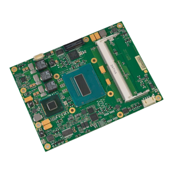
MSC C6B-8S User Manual 1.4 Module Photos Top side memory socket MAC address label Layout revision Board Identification number (BID) Fan connector Top Side View Bottom side memory socket COM Express® connector BIOS label Bottom Side View 8 / 94... -
Page 9: Technical Description
MSC C6B-8S User Manual 2 Technical Description 2.1 Key Features The MSC C6B-8S COM Express module is designed as a type 6 module according to COM Express® Module Base Specification Revision 2.1. Key features include: Module size: 125 mm x 95 mm ... -
Page 10: Block Diagram
MSC C6B-8S User Manual 2.2 Block Diagram 10 / 94... -
Page 11: Com Express Implementation
The features identified as Minimum (Min.) shall be implemented by all modules. Features identified up to Maximum (Max) may be additionally implemented by a module. The column MSC C6B-8S shows the implemented features of the MSC module. Type 6... - Page 12 MSC C6B-8S User Manual A-B Thermal Protection 0 / 1 A-B Battery Low Alarm 0 / 1 A-B Suspend 0 / 1 A-B Wake 0 / 2 A-B Power Button Support 1 / 1 A-B Power Good 1 / 1...
-
Page 13: Functional Units
MSC C6B-8S User Manual 2.4 Functional units CPUs Intel® Core i7-4700EQ (Quad Core, 2.4GHz, 6MB, SV 47W). (FCBGA-1023) Intel® Core i5-4400E (Dual Core, 2.7GHz, 3MB, SV 37W). Intel® Core i5-4402E (Dual Core, 1.6GHz, 3MB, SV 25W). Intel® Core i3-4100E (Dual Core, 2.4GHz, 3MB, SV 37W). - Page 14 MSC C6B-8S User Manual Watchdog Timer Embedded controller creates watchdog alert and system reset (programmable timeout, 1s … 10min). Optional TPM module, TPM 1.2, SLB9635. TPM (option) Fan Supply 4-pin header for support of a 12V PWM fan. Real Time Clock RTC integrated in PCH.
-
Page 15: Power Supply
2.6 Power Dissipation 2.6.1 Running Mode All measurements made by plugging the MSC C6B-8S module onto a MSC C6-MB-EVA evaluation board. The module was equipped with two 4GByte memory modules Hynix HMT451S6AFR8A-PB NO AA, 4G 1Rx8 PC3L-12800S-11-12 B4. The table below shows typical values. -
Page 16: Power Dissipation (Standby Modes)
1.1 W 0.5 W 0.5 W 2.7 System Memory The MSC C6B-8S CPU module provides two sockets for memory modules. The memory modules have to meet the following demands: 204pin unbuffered non-ECC DDR3L SO-DIMM, Raw Card B and F. -
Page 17: Mechanical Dimensions
MSC C6B-8S User Manual 2.8 Mechanical Dimensions 2.8.1 Compact module There are two height options defined in the COM Express specification: 5mm and 8mm. The height option is defined though the connectors on the baseboard. 17 / 94... -
Page 18: Thermal Specifications
MSC C6B-8S User Manual 2.9 Thermal specifications The cooling solution of a COM Express module based on a heat-spreader concept. A heat-spreader is a metal plate (typically aluminum) mounted on the top of the module. The connection between this plate and the module components is typically done by thermal interface materials like phase change foils, gap pads and copper or aluminum blocks. -
Page 19: Signal Description
MSC C6B-8S User Manual 2.10 Signal description Pins are marked in the following tables with the power rail associated with the pin, and, for input and I/O pins, with the input voltage tolerance. The pin power rail and the pin input voltage tolerance may be different. For example, the PCI group is defined as having a 3.3V power rail, meaning that the output signals will only be driven to 3.3V, but the pins are tolerant of 5V signals. -
Page 20: Ethernet
MSC C6B-8S User Manual 2.10.2 Ethernet Signal Signal Power Remark / PU/PD/SR Description Source / Target Type Level Rail Tolerance GBE0_MDI[0:3]+ Analog 3.3V Sus 3.3V Gigabit Ethernet Controller 0: Media Dependent Interface Differential I217-LM GBE0_MDI[0:3]- Pairs 0,1,2,3. The MDI can operate in 1000, 100 and 10 Mbit / sec modes. -
Page 21: Pci Express Lanes
MSC C6B-8S User Manual 2.10.4 PCI Express Lanes Signal Signal Power Remark / PU/PD/SR Description Source / Target Type Level Rail Tolerance PCIE_TX[0:6+ PCIe 3.3V AC coupled PCI Express Differential Transmit Pairs 0 through 6 PCH 82QM87 PCIE_TX[0:6]- on module... -
Page 22: Usb
MSC C6B-8S User Manual 2.10.7 USB Signal Signal Power Remark / PU/PD/SR Description Source / Target Type Level Rail Tolerance USB[0:7]+ 3.3V Sus 3.3V iPD = 15 KΩ USB differential pairs, channels 0 through 7 PCH 82QM87 USB[0:7]- ePU = 10 KΩ... -
Page 23: Lvds Flat Panel
MSC C6B-8S User Manual 2.10.9 LVDS Flat Panel Signal Signal Power Remark / PU/PD/SR Description Source / Target Type Level Rail Tolerance LVDS_A[0:3]+ LVDS LVDS Channel A differential pairs ANX1122 LVDS_A[0:3]- LVDS_A_CK+ LVDS LVDS Channel A differential clock ANX1122 LVDS_A_CK-... -
Page 24: Digital Display Interfaces
MSC C6B-8S User Manual 2.10.11 Digital Display Interfaces 2.10.11.1 Overview Type6 DDI Video Type Mapping Signal HDMI/DVI (TMDS Signaling) DDI1_PAIR0+/- DP1_LANE0+/- TMDS1_DATA2+/- DDI1_PAIR1+/- DP1_LANE1+/- TMDS1_DATA1+/- DDI1_PAIR2+/- DP1_LANE2+/- TMDS1_DATA0+/- DDI1_PAIR3+/- DP1_LANE3+/- TMDS1_DATACLK+/- DDI1_PAIR4+/- DDI1 DDI1_PAIR5+/- DDI1_PAIR6+/- DDI1_HPD DP1_HPD HDMI1_HPD DDI1_CTRLCLK/DATA_AUX+/- DP1_AUX+/-... - Page 25 MSC C6B-8S User Manual 2.10.11.2 DisplayPort Signal Signal Power Remark / PU/PD/SR Description Source / Target Type Level Rail Tolerance DP1_LANE[0:3]+ AC coupled DisplayPort Lane [0:3] differential pairs. PCH 82QM87 DP1_LANE[0:3]- off module ePD = 100kΩ DP1_AUX+ AC coupled DisplayPort Aux control channel differential pair PCH 82QM87 ePU = 100kΩ...
- Page 26 MSC C6B-8S User Manual Signal Signal Power Remark / PU/PD/SR Description Source / Target Type Level Rail Tolerance TMDS1_CTRLDATA CMOS 3.3V 3.3V ePU = HDMI/DVI Control Data. Shared with SDVO_CTRLDATA PCH 82QM87 2.2kΩ TMDS1_HPD CMOS 3.3V 3.3V HDMI/DVI Hot Plug Detect.
-
Page 27: Miscellaneous
MSC C6B-8S User Manual 2.10.12 Miscellaneous Signal Signal Power Remark / PU/PD/SR Description Source / Target Type Level Rail Tolerance ePU = 2.2 KΩ General purpose I2C port clock output I2C_CK CMOS 3.3V Sus PCH 82QM87 GPIO47 ePU = 2.2 KΩ General purpose I2C port data I/O line I2C_DAT CMOS 3.3V Sus... - Page 28 MSC C6B-8S User Manual Signal Signal Power Remark / PU/PD/SR Description Source / Target Type Level Rail Tolerance ePU = 10 KΩ SUS_STAT# CMOS 3.3V Sus 3.3V Indicates imminent suspend operation; used to notify LPC devices. PCH 82QM87 SUS_S3# CMOS 3.3V Sus 3.3V Indicates system is in Suspend to RAM state.
-
Page 29: General Purpose I/O
MSC C6B-8S User Manual 2.10.14 General Purpose I/O Signal Signal Power Remark / PU/PD/SR Description Source / Target Type Level Rail Tolerance ePU = 10 KΩ GPI[0:3] CMOS 3.3V 3.3V General purpose output pins. PCH 82QM87 Upon a hardware reset, these outputs are low. -
Page 30: Module Type Definition
MSC C6B-8S User Manual 2.10.16 Module Type Definition Signal Signal Power Remark / PU/PD/SR Description Source / Target Type Level Rail Tolerance TYPE[0:2]# Type 6 module The TYPE pins indicate to the Carrier Board the Pin-out Type that is Carrier board logic implemented on the module. -
Page 31: Power And Gnd
MSC C6B-8S User Manual 2.10.17 Power and GND Signal Signal Power Remark / PU/PD/SR Description Source / Target Type Level Rail Tolerance VCC_12V Power Primary power input: +12V (±10%) Voltage (±10%) Regulators VCC_5V_SBY Power 5V (±5%) Standby power input: +5.0V (±5%) VCC3.3V SUS... -
Page 32: Pin List For Msc C6B-8S Module (Type 6)
MSC C6B-8S User Manual 2.11 Pin List for MSC C6B-8S module (Type 6) GND (FIXED) GND (FIXED) GND (FIXED) GND (FIXED) GBE0_MDI3- GBE0_ACT# GBE0_MDI3+ LPC_FRAME# USB_SSRX0- USB_SSTX0- GBE0_LINK100# LPC_AD0 USB_SSRX0+ USB_SSTX0+ GBE0_LINK1000# LPC_AD1 GBE0_MDI2- LPC_AD2 USB_SSRX1- USB_SSTX1- GBE0_MDI2+ LPC_AD3 USB_SSRX1+... - Page 33 D107 VCC_12V A108 VCC_12V B108 VCC_12V C108 VCC_12V D108 VCC_12V A109 VCC_12V B109 VCC_12V C109 VCC_12V D109 VCC_12V A110 GND (FIXED) B110 GND (FIXED) C110 GND (FIXED) D110 GND (FIXED) = not supported on MSC C6B-8S modules. 33 / 94...
-
Page 34: Jumpers And Connectors
MSC C6B-8S User Manual 3 Jumpers and Connectors 3.1 Jumpers There are four jumpers available on the module: RTC Reset: By shorting the pins of this jumper, the RTC Clock is reset and the values of the CMOS NV-RAM are cleared. -
Page 35: Watchdog
MSC C6B-8S User Manual SPH-002T-P0.5S (AWG# 30-24), SPH-002T-P0.5L (AWG# 28-24) or SPH-004T-P0.5S (AWG# 32-28) The pinning is as following (numbering from right to left): Signal Description V12FAN +12V fan supply voltage. Input for the tacho signal of the fan (O.C.; 3.6 KΩ PU to 12V) TACHO Output of the PWM-Signal for fan speed control. -
Page 36: System Resources
MSC C6B-8S User Manual 5 System resources PCI IRQ Routing Interrupts of Controller (PCH) Slot Number IDSEL # (or Onboard Device) DEV/ Func Intel Integrated Graphic Device SA Thermal Device 1F/2 SATA #0, SATA #1, SATA RAID Controller SMBus Controller... -
Page 37: Irq Lines In Apic Mode
MSC C6B-8S User Manual IRQ Lines in APIC Mode IRQ# Available Connected to Pin Typical Interrupt Source Counter 0 Keyboard Cascade Interrupt from Slave PIC shared SCI Math processor INT A INT B INT C INT D INT E INT F... -
Page 38: Bios
MSC C6B-8S User Manual 6 BIOS 6.1.1 Introduction This guide describes the AMI Aptio Setup Startup screen and contains information on how to access Aptio setup to modify the settings which control AMI pre-OS (operating system) functions. 6.1.2 Startup Screen Overview The AMI Aptio Startup screen is a graphical user interface (GUI) that is included in AMI Aptio products. -
Page 39: The Bios Menu Structure
MSC C6B-8S User Manual 6.1.6 The BIOS Menu Structure The BIOS Menu is structured in the following way: Main MSC Board Info Hardware Monitoring Measurement System Information Advanced CPU Configuration Trusted Computing ACPI Settings PCH-FW Configuration AMT Configuration SMART Settings... - Page 40 MSC C6B-8S User Manual 6.1.6.1 The Menu Bar The Menu Bar at the top of the window lists these selections: Menu Items Description Main Use this menu for basic system information. Advanced Use this menu to set the Advanced Features available on your system’s chipset.
- Page 41 MSC C6B-8S User Manual used to select a value from a Pop Up menu. The Save Values commands in the Exit Menu save the values currently displayed in all the menus. 6.1.6.4 Display a submenu To display a submenu, use the arrow keys to move the cursor to the sub menu you want.
-
Page 42: The Main Menu
MSC C6B-8S User Manual 6.1.7 The Main Menu You can make the following selections on the Main Menu itself. Use the sub menus for other selections. Feature Options Description Bios Vendor Informative Shows the Bios Vendor Core Version Informative Shows the Aptio Core Version... - Page 43 MSC C6B-8S User Manual 6.1.7.1 MSC Board Info Feature Options Description Manufacturer MSC Technologies GmbH Board Name Informative Shows the board name Board Revision Informative Shows the board revision Bios Version Informative Shows the bios version Serial Number Informative Shows the boards serial number...
- Page 44 MSC C6B-8S User Manual 6.1.7.2 Hardware Monitoring Measurement Note: The value shown in the BIOS and EAPI for the temperatures, is the temperature read by the Board controller from a sensor mounted on the board. Feature Options Description CPU Temperature...
-
Page 45: The Advanced Menu
MSC C6B-8S User Manual Feature Options Description SPI Clock Frequency Informative Shows the SPI clock frequencies. 6.1.8 The Advanced Menu Feature Options Description PCI Subsystem Settings Submenu PCI, PCI-X and PCI Express settings ACPI Settings Submenu System ACPI Parameters Trusted Computing... - Page 46 MSC C6B-8S User Manual Feature Options Description Embedded Controller Submenu Submenu for Embedded Controller Features Features Fan Configuration Submenu Submenu for Fan Configuration Serial Port Console Submenu Serial Port Console Redirection Redirection settings Intel ICC Submenu Integrated clock control options...
- Page 47 MSC C6B-8S User Manual Feature Options Description Hardware Prefetcher Enabled, Disabled Enable the Mid Level Cache (L2) streamer prefetcher. Enable the Mid Level Cache (L2) Adjacent Cache Line P Enabled, Disabled prefetching of adjacent cache lines. CPU AES Enabled, Disabled...
- Page 48 MSC C6B-8S User Manual Feature Options Description 2-Core Ratio Limi Value This limit is for 2 cores active. 0 means using the factory-configured value. 3-Core Ratio Limi Value This limit is for 3 cores active. 0 means using the factory-configured value.
- Page 49 MSC C6B-8S User Manual Feature Options Description Package C State limit C0-C7s, Auto Package C State limi LakeTiny Feature Enabled, Disabled Enable/Disable LakeTiny for C state configuration ACPI CTDP BIOS Enabled, Disabled Enable/Disable ACPI CTDP BIOS supoor Configurable TDP TDP Nominal, TDP Down,...
- Page 50 MSC C6B-8S User Manual Feature Options Description TPM state Enabled, Disabled Turn TPM Enable/Disable. NOTE: Your Computer will reboot during restart in order to change State of TPM. Pending Operation None, Schedule an operation for the Security Enable take ownership Device.
- Page 51 MSC C6B-8S User Manual 6.1.8.5 Firmware Update Configuration Submenu Feature Options Description Me FW Image Re-Flash Enabled, Disabled Enable/Disable ME FW Image Re- Flash function. Note: Enable this option if Bios update requires an update of the Intel Management Engine (ME). See the Readme.txt which comes with...
- Page 52 MSC C6B-8S User Manual 6.1.8.6 AMT Configuration Feature Options Description Intel AMT Enabled, Disabled Enable/Disable Intel (R) Active Management Technology BIOS Extension. Note: iAMT H/W is always enabled. This option just controls the BIOS extension execution. If enabled, this requires additional...
- Page 53 MSC C6B-8S User Manual Feature Options Description PET Progress Enabled, Disabled Users can Enable/Disable PET Events progress to receive PET events or not. AMT CIRA Timeout Value OEM defined timeout for MPS connection to be established. 0 - use the default timeout value of 60 seconds.
- Page 54 MSC C6B-8S User Manual Feature Options Description Serial Port for Out-of- Enabled, Console Redirection Enable or Disable Band Disabled Management/Windows Emergency Management Service (EMS) Console Redirection Console Redirection Submenu The settings specify how the host computer and the Settings remote computer (which the user is using) will exchange data.
- Page 55 MSC C6B-8S User Manual 6.1.8.8.1 Console Redirection Settings COM0 Submenu Feature Options Description Terminal Type ANSI, VT100, Emulation: ANSI: Extended ASCII char set. VT100: VT100+, VT- ASCII char set. VT100+: Extends VT100 to support UTF8 color, function keys, etc. VT-UTF8: Uses UTF8 encoding to map Unicode chars onto 1 or more bytes.
- Page 56 MSC C6B-8S User Manual 6.1.8.8.2 Console Redirection EMS Feature Options Description Out-of-Band Mgmt Port COM0, COM1 Microsoft Windows Emergency Management Services (EMS) allows for remote management of a Windows Server OS through a serial port. Terminal Type ANSI, VT100, Emulation: ANSI: Extended ASCII char set. VT100: VT100+, VT- ASCII char set.
- Page 57 MSC C6B-8S User Manual 6.1.8.10 Clock Submenu Feature Options Description New Spread percentage 0-50 Requested SSC in percent in 0.01% increments. Changes will not be applied unless ‘Accept changes’ is pressed. Apply settings Changes will be applied immediately, but forgotten immediately after reboot.
- Page 58 MSC C6B-8S User Manual 6.1.8.13 SATA Configuration Feature Options Description SATA Controller(s) Enabled, Disabled Enable or disable SATA DEVICE SATA Mode Selection AHCI, IDE, RAID Software Feature Mask Configuration For more information see also technotes in chapter 6.7 Aggressive LPM Support...
- Page 59 MSC C6B-8S User Manual Feature Options Description OPROM UI and Banner Enabled, Disabled If enabled, then the OROM UI is shown. Otherwise, no OROM banner or information will be displayed if all disks and RAID volumes are Normal HDD Un...
- Page 60 MSC C6B-8S User Manual Feature Options Description SERR# Generation Enabled, Disabled Enables or disables PCI Device to generate SERR#. Above 4G Decoding Enabled, Disabled Enables or Disables 64bit capable Devices to be Decoded in Above 4G Address Space (Only if System Supports 64 bit PCI Decoding).
- Page 61 MSC C6B-8S User Manual 6.1.8.16 Network Stack Feature Options Description Network stack Enabled, Enable/Disable UEFI network stack Disabled Ipv4 PXE Support Enabled, Enable Ipv4 PXE Boot Support. If disabled IPV4 Disabled PXE boot option will not be created Ipv6 PXE Support Enabled, Enable Ipv6 PXE Boot Support.
- Page 62 MSC C6B-8S User Manual 6.1.8.18 NVMe Configuration Feature Options Description Controller x Informative NVMe controller and Drive information 6.1.8.19 USB Configuration Feature Options Description Legacy USB Support Auto, Enabled, Disabled Enables Legacy USB support. AUTO option disables legacy support if no USB devices are connected.
- Page 63 MSC C6B-8S User Manual Feature Options Description Device power-up delay Auto, Manual Maximum time the device will take before it properly reports itself to the Host Controller. 'Auto' uses default value: for a Root port it is 100 ms, for a Hub port the delay is taken from Hub descriptor.
- Page 64 MSC C6B-8S User Manual Feature Options Description COM B Setting: Auto, Resource setting for COM A on Winbond SIO I/O 2F8h, IRQ 3 I/O 3F8h, IRQ 3, 4, 5, 6, 7 ,10, 11, 12 I/O 2F8h, IRQ 3, 4, 5, 6, 7 ,8,10,...
- Page 65 MSC C6B-8S User Manual 6.1.8.22 EC Hardware Monitoring Feature Options Description CPU Fan Control Manual, Temperature Define how the fan should be controlled: based manually set to a fixed duty cycle, or temperature based auto control. Temperature Source CPU, System, Board, Fan is auto controlled by either CPU, board CPU &...
- Page 66 MSC C6B-8S User Manual CPU/System/Board 60°C, 70°C, 80°C, Temperature threshold (in degrees Celsius) Temperature Limit T3 90°C, 100°C at which the fan should be set to maximum [°C] speed duty cycle. Note: This option depends on selected temperature source ( CPU/System/Board or a combination of these) 60°C –...
- Page 67 MSC C6B-8S User Manual PWM mid Fan running with medium speed (typically 50%) PWM max Fan running with maximum speed (typically 100%) Temperature zone T<T1, Fan stopped Temperature zone T1<T<T2, Fan running with minimum speed Temperature zone T2<T<T3, Fan running with medium speed Temperature zone T2<T<T3, Fan running with maximum...
- Page 68 MSC C6B-8S User Manual Reset Timeout 1s,10s,30s, Select the timeout value after which the watchdog 1min,5min will be executing its reset action. This timeout will start to countdown after the event timeout expired. Watchdog Action on Reset System, Select the action that should be initiated after a reset...
-
Page 69: The Chipset Menu
MSC C6B-8S User Manual 6.1.9 The Chipset Menu Feature Options Description Flat Panel Configuration Submenu Flat Panel Configuration System Agent (SA) Submenu System Agent (SA) parameters Configuration PCH-IO Configuration Submenu PCH parameters 6.1.9.1.1 Flat Panel Configuration Feature Options Description Flat Panel Type... - Page 70 MSC C6B-8S User Manual Feature Options Description Backlight Control Enabled, Backlight may be controlled by either Chipset or Disabled Embedded Controller Enabled = Embedded Controller Disabled = Chipset Backlight upon Boot Enabled, Switch Backlight On or Off upon boot Disabled...
- Page 71 MSC C6B-8S User Manual Feature Options Description Memory Configuration Submenu Memory Configuration settings. Memory Thermal Submenu Memory Thermal Configuration settings. Configuration GT- Power Management Submenu GT- Power Management Control settings. Control 6.1.9.1.4 Graphics Configuration Feature Options Description Graphics Turbo IMON C Value...
- Page 72 MSC C6B-8S User Manual 6.1.9.1.5 LCD Control Submenu Feature Options Description Primary IGFX Boot VBIOS Default, Select the Video Device which will be activated Display CRT, EFP, LFP, during POST. EFP 3, EFP 2, This has no effect if external graphics present.
- Page 73 MSC C6B-8S User Manual 6.1.9.1.7 NB PCIe Configuration Submenu Feature Options Description PCIe Bifurcation X8x4x4, x8x8, PCI Express Bifurcation PEG0 - 2 – Gen X Auto, Gen1, Configure PEG0 B0:D1:f0 Gen1-Gen2-Gen3 Gen2, Gen3 Note: This option is available for PEG0, PEG1 and...
- Page 74 MSC C6B-8S User Manual Feature Options Description Enabled, Always re-search Gen3 Always re-search Gen3 Preset, even it has been Disabled Eq Preset done once Auto, 0-9, 7,3,5 Number of Presets to Choose between 7,3,5 and 0-9, auto = current Intel...
- Page 75 MSC C6B-8S User Manual Feature Options Description Max TOLUD Dynamic, 1GB - Maximum Value of TOLUD. Dynamic assignment 3,25GB in would adjust TOLUD automatically based on largest 0.25GB steps MMIO length of installed graphic controller Note:If there is a problem with an external graphic...
- Page 76 MSC C6B-8S User Manual Feature Options Description RMT Crosser Support Enabled, Enable or disable RmtCrosserEnable support. Disabled MRC Fast Boot Enabled, Enable or disable MRC fast boot. Disabled DIMM Exit Mode Auto, Slow exit, DIMM Exit Mode Control Fast exit...
- Page 77 MSC C6B-8S User Manual GT – Power Management Submenu 6.1.9.1.10 Feature Options Description RC6(Render Standby) Enabled, Check to enable render standby support. Disabled 77 / 94...
- Page 78 MSC C6B-8S User Manual 6.1.9.2 PCH-IO Configuration Feature Options Description PCI Express Submenu PCI Express Configuration settings Configuration USB Configuration Submenu USB Configuration settings PCH Azalia Submenu PCH Azalia Configuration settings. Configuration Bios Security Submenu Bios Security Configuration settings Configuration...
- Page 79 MSC C6B-8S User Manual Feature Options Description Port 80h Redirection LPC Bus, PCI Control where the Port 80h cycles are sent 6.1.9.2.1 PCI Express Configuration Submenu Feature Options Description PCI Express Clock Gate Enabled, Enable or disable PCI Express Clock Gating for Disabled each root port.
- Page 80 MSC C6B-8S User Manual 6.1.9.2.2 PCI Express Root Port x (0-7) Submenu Feature Options Description PCI Express Root Port Enabled, Control the PCI Express Root Port. Disabled ASPM Support Disabled,L0s, Set the ASPM Level: Force L0 - Force all links to L0...
- Page 81 MSC C6B-8S User Manual Feature Options Description Reserved Memory 1-20MB Reserved Memory and Prefetchable Memory (1- 20MB) Range for this Root Bridge. Prefetchable Memor Value Reserved I/O Value Reserved I/O (4K/8K/12K/16K/20K) Range for this Root Bridge. PCIE LTR Enabled, Prefetchable Memory Range for this Root Bridge...
-
Page 82: Boot
MSC C6B-8S User Manual 6.1.9.2.4 PCH Azalia Configuration (HD Audio) Feature Options Description Azalia Auto, Enabled, Control Detection of the Azalia device. Disabled Disabled = Azalia will be unconditionally disabled Enabled = Azalia will be unconditionally Enabled Auto = Azalia will be enabled if present, disabled otherwise. - Page 83 MSC C6B-8S User Manual Feature Options Description Fast Boot Enabled, Enables/Disables boot with initialization of a minimal Disabled set of devices required to launch active boot option. Has no effect for BBS boot options. For more information see also technotes in chapter...
-
Page 84: Security
MSC C6B-8S User Manual Feature Options Description Boot Option #1… Device x Sets the system boot order. Please note that UEFI boot entries will always have the highest priority. This list will be updated during next boot depending on the settings in the Advanced Boot Device Selection. -
Page 85: The Save & Exit Menu
MSC C6B-8S User Manual 6.1.12 The Save & Exit Menu The following sections describe each of the options on this menu. Save Changes and Exit After making your selections in the setup menus, always select "Exit Saving Changes". This procedure stores the selections displayed in the menus in a flash. The next time you boot your computer, the BIOS configures your system according to the setup selections stored in flash. - Page 86 MSC C6B-8S User Manual Save changes done so far as User defaults. Boot Override It will display all the available boot options from the Boot Option List. The user can select any of the options to select to the particular device and boot directly from it.
-
Page 87: Bios And Firmware Update
MSC C6B-8S User Manual 6.2 BIOS and Firmware Update If a System-BIOS update is required please follow these instructions: Bios Update from DOS: Create a bootable DOS disk, USB Stick or hard disk and unpack the update tool AFUDOS.exe from AFUx64_303.msi ... -
Page 88: Blind Restoration Of Bios Default Settings (No Display Available)
MSC C6B-8S User Manual When the Bios update has finished, reboot the system. Note: If an EFI Shell is needed for Bios updates, please contact MSC Technical support. Note: After the system has been updated, the setup settings will be changed to defaults , and therefore it may be necessary to enter Setup to reconfigure the system settings. -
Page 89: Bios Recovery
MSC C6B-8S User Manual 6.5 Bios Recovery If a Bios update will be interrupted (e.g. due to power loss) and the update has not been finished, it can be that the system will not boot. In this case it is possible to restore the Bios with the following method: 1. -
Page 90: Tech Notes
MSC C6B-8S User Manual 6.7 Tech Notes 1. Intel® Rapid Storage Technology With Intel Rapid Storage Technology you can take use of the advantages of AHCI and RAID. Through AHCI, storage performance is improved with Native Command Queuing (NCQ). AHCI also delivers longer battery life with Link Power Management (LPM), which can reduce the power consumption of the chipset and Serial ATA (SATA) hard drive. - Page 91 MSC C6B-8S User Manual Note: If EIST is disabled in setup, the CPU will run at its maximum speed. Turbo Boost Technology won’t be available. 4. Turbo Boost Technology 2.0 Intel Turbo Boost is a technology that enables the processor to run above its base operating frequency via dynamic control of the CPU's "clock rate".
- Page 92 MSC C6B-8S User Manual models opens up that reduce costs, increase management efficiency, strengthen security, while making your computing infrastructure more resilient in the event of a disaster. For more information about the technology please visit: http://www.intel.com/technology/virtualization/ VT-d supports the remapping of I/O DMA transfers and device-generated interrupts. The architecture of VT-d provides the flexibility to support multiple usage models that may run un-modified, special-purpose, or "virtualization aware"...
-
Page 93: Eapi
MSC C6B-8S User Manual 11. List of references 4. Turbo Boost http://en.wikipedia.org/wiki/Intel_Turbo_Boost 5. ASPM http://en.wikipedia.org/wiki/Active_State_Power_Management 8. Intel VT and VT-d http://ark.intel.com/VTList.aspx http://www.intel.com/technology/itj/2006/v10i3/2-io/7-conclusion.htm 10. TPM http://en.wikipedia.org/wiki/Trusted_Platform_Module 7 EAPI The "Embedded Application Programming Interface" (EAPI) used by this module provides a standardized interface for customer applications. This interface allows a user mode application access to hardware specific information as well as hardware resources. -
Page 94: Troubleshooting
MSC C6B-8S User Manual 8 Troubleshooting Problem 1: USB 3.0 stick causes hang at boot time Some USB 3.0 sticks/disks may cause BIOS to hang at post code 0xB4, if XHCI mapping mode is not set to enabled. Solution: Please check for firmware update of the USB device. Alternatively the setting for XHCI mapping mode could be changed to enabled in the BIOS setup.
Need help?
Do you have a question about the MSC C6B-8S and is the answer not in the manual?
Questions and answers