
Related Manuals for Electrolab DLS 2100 Series

Summary of Contents for Electrolab DLS 2100 Series
- Page 1 USER MANUAL DLS 2100 PRODUCT LINE RU FLEX SENSOR W/ HLS EL 29126_RevC © 2020, Electrolab, Inc. All Rights Reserved. Last Updated: 02/2020...
- Page 2 License Agreement between the user and Electrolab, Inc. Electrolab, Inc. makes no representations of warranties with respect to the contents hereof and specifically disclaims any implied warranties of merchantability of fitness for any particular purpose. Electrolab, Inc.
-
Page 3: Table Of Contents
Report Battery Voltage ....................... 16 Table 1. Read/Write Registers ......................17 Table 2. Holding Registers........................ 20 Table 3. Holding Registers (2 x 16 bit) ..................... 22 Table 4. Warning Codes ........................24 Table 5. Error Codes ......................... 24 © 2020, Electrolab, Inc. March 2020... - Page 4 © 2020, Electrolab, Inc. March 2020...
- Page 5 TX/RX+ from the sensor to TX/RX+ on the receiving equipment and TX/RX- from the sensor to TX/RX- on the receiving equipment. The voltage supply can be connected to a switched output so power is applied only during sensor polling. © 2020, Electrolab, Inc. March 2020...
-
Page 6: Sensor Assembly
7. Rest the 2-piece shaft collar clamp at the top of the cord grip and tighten the bolts using a ¼” hex wrench to prevent the sensor from slipping over time. CAUTION: CONFIRM THAT POWER IS OFF before proceeding. © 2020, Electrolab, Inc. March 2020... -
Page 7: Electrical Connection
2. Using the white depressor tool, install the six wires (4-wire communication) or four wires (2- wire communication) as directed in the connection (hook-up) diagram in Figure 3. 3. Plug in the connector. Route wires away from the housing threads and screw in the housing cover. © 2020, Electrolab, Inc. March 2020... - Page 8 Push the gasket down to seat in the cord grip body. The pull-tab should be loose, not taut. If the pull-tab is taut, push the 3/16” tube into the gasket until it is loose. Tighten the cord grip nut. HLS INSTALLATION COMPLETE. © 2020, Electrolab, Inc. March 2020...
- Page 9 Lift the sensor up and down a few times before resetting the sensor in the tank and retightening the cord grip and 2-piece shaft collar clamp. You are now ready to set the initial offset. © 2020, Electrolab, Inc. March 2020...
- Page 10 9. Once the level offsets are entered, there is no further calibration required unless the DLS is removed and reinstalled in another tank. EXAMPLE: If the actual level is 156.25” and the DLS reading is 146.50”, then the offset value will be 9.75” (156.25-146.50=9.75). © 2020, Electrolab, Inc. March 2020...
- Page 11 An incorrect number of floats are programmed. Check the sensor protocol command list to reprogram the sensor with the correct information. Sensor has an HLS float installed and is not programmed for High Level. © 2020, Electrolab, Inc. March 2020...
-
Page 12: Command Syntax
5 = Transmit to slave processor for level failed 6 = Transmit to slave processor for temperature failed 7 = Receive from slave processor of level failed 8 = Receive from slave processor of temperature failed 9 = No slave processors responding © 2020, Electrolab, Inc. March 2020... - Page 13 (i.e., only one float is present or both floats are abutted). Note: The number of decimal places in a data field implies nothing about the accuracy of the data (i.e., levels are not accurate to 0.01 inches). © 2020, Electrolab, Inc. March 2020...
-
Page 14: Report Level And Temperature Continuously (Factory Diagnostics)
Assign Unit Number UuuNnn uu = unit number (from 00 to 31) nn = new unit number Note: Unit number 00 is not valid in Modbus RTU mode Response: UuuNOK uu = newly assigned unit number © 2020, Electrolab, Inc. March 2020... -
Page 15: Assign Unit Number To Sensor With The Corresponding Sn# (V3.15 Or Higher)
The Minus (-) must precede the offset value if required. If no decimal places are required, then you do not need to add to value. Note: "O" in the command is the letter O and not the number zero Response: UuuLOOK © 2020, Electrolab, Inc. March 2020... -
Page 16: Set Temperature Offset
= unit number x = 0 will set the level error report to be 999.99. This is the default setting. x = 1 will set the level error report to be 000.00. Response: UuuSETERROK © 2020, Electrolab, Inc. March 2020... -
Page 17: Set The Modbus 16 Bit Unsigned Integer, 32 Bit Or 2 X 16 Bit Floating Point Mode
Response: UuuESDONOK ESD mode was successfully activated Exit High Level Electronic Shut Down (ESD Mode) (Version 3.15 and Higher) UuuESDOFF Response: UuuESDOFFOK ESD mode exit successfully Note: UuuESDON0 also turns off ESD mode © 2020, Electrolab, Inc. March 2020... -
Page 18: Configuration Request Commands
= distance between switches as integral tenths of an inch (e.g., 5 = 0.5 inches, 10 = 1 inches) UuuR? Response: UuuRmmm uu = unit number mmm = delay Report Total Switches UuuS? Response: UuuSssss uu = unit number ssss = total number of switches in the sensor © 2020, Electrolab, Inc. March 2020... -
Page 19: Report Receive To Transmit Delay
UuuSN? Response: UuuSNxxxxxxx uu = unit number xxxxxxxx = serial number. Report Unit Number Corresponding to Serial Number (Version 3.15 and Higher) UsssssssN? sssssss = seven-digit serial number Response: UsssssssNuu uu = unit number © 2020, Electrolab, Inc. March 2020... -
Page 20: Report Sensor Health Status (Version 3.15 And Higher)
= 1 is set for 32 bit floating point mode. x = 2 is set for 2x16 bit floating point mode (v3.14 and higher) Report Battery Voltage UuuBV? Response: UuuBVvv.vV uu = unit number vv.v = battery voltage in volts © 2020, Electrolab, Inc. March 2020... - Page 21 1000 bbls/in setting: 167 Unsigned Top level offset x Factory 40117 16 bit Signed 100: -9999 to 9999 setting: 0 Bottom level offset x Factory 40118 16 bit Signed 100: -9999 to 9999 setting: 0 © 2020, Electrolab, Inc. March 2020...
- Page 22 Unsigned 1= Sensor errors or (v3.15 and low battery higher) 16 bit Group 0 top 40137 Read only Unsigned (v3.15 and higher) 16 bit Group 0 bottom 40138 Read only Unsigned (v3.15 and higher) © 2020, Electrolab, Inc. March 2020...
- Page 23 Group 2 bottom 40142 Read only Unsigned (v3.15 and higher) Group 3 top 40143 Read only 16 bit Unsigned (v3.15 and higher) 16 bit Group 3 bottom 40144 Read only Unsigned (v3.15 and higher) © 2020, Electrolab, Inc. March 2020...
- Page 24 Read Only 16 bit Unsigned integer or 32 bit floating point Temperature4 Temperature4 44000 3999 Read Only 16 bit Unsigned integer or 32 bit floating point Temperature5 44001 4000 Read Only Temperature5 16 bit Unsigned © 2020, Electrolab, Inc. March 2020...
- Page 25 (*100 for 16 bit) 16 bit Unsigned integer or 32 bit floating point Error 44006 4005 Read Only 16 bit Unsigned Register: integer (See Notes) Warnings 44007 4006 Read Only 16 bit Unsigned Register: integer (See Notes) © 2020, Electrolab, Inc. March 2020...
- Page 26 Oil Level in Tank(top-bottom) 45006 5005 Floating point lower two bytes Only (v3.14 and higher) Total Volume 45007 5006 Read Total Volume(top level x K factor) Floating point upper two bytes (top level x K Only © 2020, Electrolab, Inc. March 2020...
- Page 27 Temperature7 Only Floating point lower two bytes Read Temperature8 45027 5026 (v3.14 and higher) Temperature8 Only Floating point upper two bytes Read 45028 5027 (v3.14 and higher) Temperature8 Only Floating point lower two bytes © 2020, Electrolab, Inc. March 2020...
- Page 28 107 to “2”, and will set the device hold registers 45001(5000) to 45034(5033) to 2 x 16 bit floating point format. Reading register 107 will return “0” for 16 bit, “1” for 32 bit floating point, and “2” for 2 x 16 bit floating point format. © 2020, Electrolab, Inc. March 2020...
- Page 29 Pressure: 40 psi: standard Communication: RS485 Two- or four-wire communications Baud rate and parity programmable (up to 57600 baud on v.3.15 and higher) 4-20mA signal available when connected to digital-to-analog converter board Wireless capable © 2020, Electrolab, Inc. March 2020...
- Page 30 3 in. diameter; required weight can vary based on sensor length Wiring: 18 AWG recommended for digital circuits Classification: Class I, Div .1, Group D Hazardous Locations (when connected to an approved intrinsically safe barrier) Certification: ANSI/UL-913, 7 Edition CAN/CSA C22.2, No. 157 © 2020, Electrolab, Inc. March 2020...
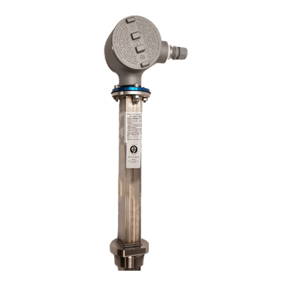
- Page 31 RU Flex 2100 DLS Reference Illustrations Figure 1 - Model 210 0DLS RU Flex w/ HLS © 2020, Electrolab, Inc. March 2020...
- Page 32 Figure 2 - Model 2100 DLS RU Flex w/ HLS Assembly Diagram © 2020, Electrolab, Inc. March 2020...
- Page 33 NATIONAL ELECTRIC CODE. AND MUST BE TERMINATED W ITHIN 18" OF THE FINISHED GRADE. 13.) ELECTRODE CONNECTION AND CABLE SIZING SHOULD BE MADE PER SECTION 250.66 OF THE: NATIONAL ELECTRIC CODE. Figure 3 - IS Barrier Connection Diagram, 4-wire © 2020, Electrolab, Inc. March 2020...
- Page 34 Figure 4 - Control Drawing 2191-001 © 2020, Electrolab, Inc. March 2020...
- Page 35 Contr ol equipment must not use or gener ate mor e than 25V r ms or dc with r espect to ear th. CAP ALL UNUSED PORT FITTINGS ON THE EXPLOSION PROOF HOUSING. CONNECT GROUND STRAP FROM HERE TO EARTH GROUND Figure 5 - Control Drawing 2191-002 © 2020, Electrolab, Inc. March 2020...
- Page 36 Example: If there are 3 tanks on one location, then specify that the level sensors be addressed U01, U02, and, U03. Alternate numbering sequences may be chosen. If no unit numbers are specified, then default will be Unit 01. © 2020, Electrolab, Inc. March 2020...
- Page 37 Contact Information For further information or for assistance, please contact: Electrolab, Inc. 159 Enterprise Parkway Boerne, Texas 78006 Phone: (210) 824-5364 TF: (888) 301-2400 insidesales@electrolabcontrols.com Email: www.electrolabcontrols.com © 2020, Electrolab, Inc. March 2020...
Need help?
Do you have a question about the DLS 2100 Series and is the answer not in the manual?
Questions and answers