Table of Contents
Advertisement
Quick Links
Advertisement
Table of Contents

Related Manuals for Eskon EPA 100

Summary of Contents for Eskon EPA 100
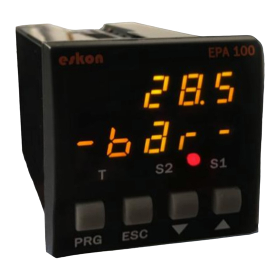
- Page 1 EPA 100 PROCESS CONTROL DEVICE • 2 x 5 Digit Display Screen • 0-10V, 4-20mA, 0-20mA, 3.33mV / V, 2mV 2.5mV / V, Potentiometric, USER CANopen Sensor Input Options • Digital Filter, Tare • Optional: Serial Communication, MANUAL Analog Output...
-
Page 2: Table Of Contents
1. INDEX INDEX ............................... 2 TECHNICAL SPECIFICATIONS ......................4 ELECTRICAL SPECIFICATIONS ....................4 2.2 MECHANICAL MEASUREMENTS ....................5 CONNECTIONS ..........................7 FRONT PANEL DEFINITIONS ......................8 MENU TREE............................9 SETUP ............................. 10 CONNECTING THE SENSOR TO THE DEVICE ................11 6.1.1 Connections of the potentiometer:................ - Page 3 DIGITAL OUTPUT SETTINGS (COMMUNICATION) ..............19 6.6.1 UART Settings ........................ 19 6.6.2 CANopen Settings ......................19 SECURE MENU ........................19 6.7.1 Hide Menu (HIDE) ......................19 6.7.2 Menu Lock (LOCK) ......................20 6.7.3 Password Determination (PASS)..................20 6.7.4 Return to Factory Settings (FTRY) .................. 20 6.7.5 Restart the Device (RESET) ....................
-
Page 4: Technical Specifications
2. TECHNICAL SPECIFICATIONS 2.1 ELECTRICAL SPECIFICATIONS 24 V 50/60 Hz AC/DC Supply Voltage 85-265 V 50/60 Hz 9 VA / 2,7 Watt Maximum Power Usage Pot: mV/V: 10 V Sensor Supply Voltage 0-10V: 24 V 4-20 mA: 24 V CANopen: 24 V Max Sensor Supply Current 100 mA... -
Page 5: Mechanical Measurements
2.2 MECHANICAL MEASUREMENTS Dimensions 48 x 48 x 96 mm Weight 200 gr. It is fixed to the panel with the feet at the top and Assembly bottom. 0 to 50 °C Operating temperature -10 °C to 60 °C Storage temperature Protection Class IP60 Front Panel, IP20 Back Panel... - Page 6 SAFETY WARNINGS 1. Follow the instructions and warnings in the user guide. 2. Please check the power supply type before connects energy to the device. 3. Please the device mounted on panel against dangers of fall, snap, shake during working. 4.
-
Page 7: Connections
3. CONNECTIONS Digital Connections Analog Outputs RS485 4-20 mA 4-20 mA RS232 Output Output USB HID USB CONNEKTOR (B Type 0-10 V 0-10 V FEMALE) Output Output USB CONNEKTOR (B Type USB VIRTUAL FEMALE) Tare Input Tare Input CANopen HIGH SENSOR Potentiometer 1 No... -
Page 8: Front Panel Definitions
4. FRONT PANEL DEFINITIONS 1) PRG ( ): Programming button. It is used to enter the menus or confirm the entered values. 2) ESC ( ): Escape, exit and backspace key. Used to go back or exit a parent menu. 3) DOWN ( ): Down key. -
Page 9: Menu Tree
5. MENU TREE Top Menu Sub Menu . . . ... -
Page 10: Setup
6. SETUP The recommended installation steps are as follows. 1. Step ELECTRICAL CONNECTIONS See Page 11. 2. Step CALIBRATION See Page 13 3. Step ENTERING RELAY SET VALUE See Page 16. 4. Step ANALOG OUTPUTS SETTING See Page 18. 5. Step COMMUNICATION SETTINGS See Page 19. -
Page 11: Connecting The Sensor To The Device
6.1 CONNECTING THE SENSOR TO THE DEVICE 6.1.1 Connections of the potentiometer: 6.1.2 Connections of 4-20mA or 0-10 V sensors:... -
Page 12: Connections Of Mv / V Ratiometric Sensor
6.1.3 Connections of mV / V Ratiometric Sensor:... -
Page 13: Calibrating Device
6.2 CALIBRATING DEVICE Press and hold the PRG key to switch to the programming menu. 6.2.1 Determining Scale Value When your device is calibrated to its factory settings, it operates at a value range of 0-100. That is, the smallest reading on the sensor shows 0 on the screen and 100 on the screen. You can change the scale from this menu. -
Page 14: Calibration Method Determination
Example: (Press and hold the PRG key while the device is in operating mode) . . . . The decimal point Press and hold the UP and DOWN The value in the starts flashing. Use keys to move to the next step. -
Page 15: Automatic Calibration
6.2.3.2 Two-point calibration In the two-point calibration option, only the maximum and minimum points are selected. For example; When calibrating a 10 cm linear potentiometer, the potentiometer is set to the minimum point in the fully closed position, while the potentiometer is fully open. 6.2.3.3 Multi (segmented) calibration With the multiple calibration option, you can calibrate your device at up to 10 different points. -
Page 16: Enter Relay Set Value
6.3 ENTER RELAY SET VALUE Your device has two relays in total with two contacts, normally open and normally closed. You can use the relay contacts in five different functions depending on your need. These functions are described in 6.4.1 6.3.1 Relay 1 Output Settings (OUT-1) ... -
Page 17: Transition To Programming Mode
. (Press and hold) . . 6.4 TRANSITION TO PROGRAMMING MODE . 6.4.1 Selection of Relay Function This function selection determines when the relay output will switch on and switch off according to the set values. -
Page 18: Delay
NO. (Normally Open) indicates that the relay is normally open. 6.5 ANALOG OUTPUT SETTINGS If your EPA 100, which is specially manufactured according to your order, has analog output module, you can make the necessary settings from this menu. 6.5.1 Analog Output Type Selection ... -
Page 19: Analog Output Scale Setting
6.6.2 CANopen Settings Here you can set the baud rate, Node ID, Heartbeat, PDO etc. of your device related to CANopen protocol. For more information on CANopen, see the EPA 100-CANopen booklet. 6.7 SECURE MENU 6.7.1... -
Page 20: Menu Lock (Lock)
6.7.4 Return to Factory Settings (FTRY) You can return the EPA 100 to its factory settings at any time. Press PRG key to come to this menu to return to the factory settings. Here you are going to face the PASS? You need to enter 12345, which is the factory password, not the user password you specified on the password screen. -
Page 21: Other Setting
7.1.2.1 Tare Input If your EPA 100, which is manufactured specifically for your order, has the Digital Tare Input module, you can make settings from the INPUT menu under the Tare menu. The EDGE option determines which edge of the edge signal coming from the mode will activate the edge function. -
Page 22: Screen Refresh Rate (Refrs)
7.1.4 Preventing Unstability on the Screen (FILTR) The EPA 100 is programmed to show the signals received from the sensor connected to it in the most accurate way by processing them with special algorithms. But; You may be able to solve this problem with the value tremble filtering method which appears on the screen for a variety of reasons such as noise in the vicinity, disturbances in the sensor. -
Page 23: Operation Module Functions
8. OPERATION MODULE FUNCTIONS Your EPA 100 process controller runs in two different modes. Your device is in 'operating mode' while the initial value of the sensor readout is displayed; In the 'programming mode' on the screen where the settings are changed and the parameters are changed. In this section, the functions in operating mode are explained. -
Page 24: Product Coding
9. PRODUCT CODING When ordering your EPA 100 process controller, you can use the following coding format. Analog Output Signal Type Empty – No Analog Output V0 - 0-10V output V1 - 0-5V output Supply Voltage V3 - 0.5-4.5V output... -
Page 25: Warranty Document
10. WARRANTY DOCUMENT Product: EPA 100 3,33 mV/V RS-232 2,5 mV/V RS-485 2 mV/V Tare Input USB Virtual 0-10 V Çıkış CANopen 4-20 mA Çıkış Serial Number : …………………………………… This product is warranted against production errors for two years. Out-of-warranty...
Need help?
Do you have a question about the EPA 100 and is the answer not in the manual?
Questions and answers