Advertisement
Quick Links
Advertisement

Related Manuals for FirePro FP-20SE

Summary of Contents for FirePro FP-20SE
- Page 1 Installation, Wiring and Earthing Guidelines for Cylindrical Aerosol units Version 2, 24-06-2016...
- Page 2 General Installation Guide Line about the FirePro Aerosol Generators FP-20SE/T/TH, FP-40S/T, FP-80S/T,FP-100S, FP-200S,FP-500S. FP-20SE/T/TH: Step 1: Take the “Bracket” and place it on the aerosol generator. Step 2: Align “Bracket” holes with surface material holes. Step 3: Select type of screws suitable to the surface material to be fixed (these screws are not supplied with the kit).
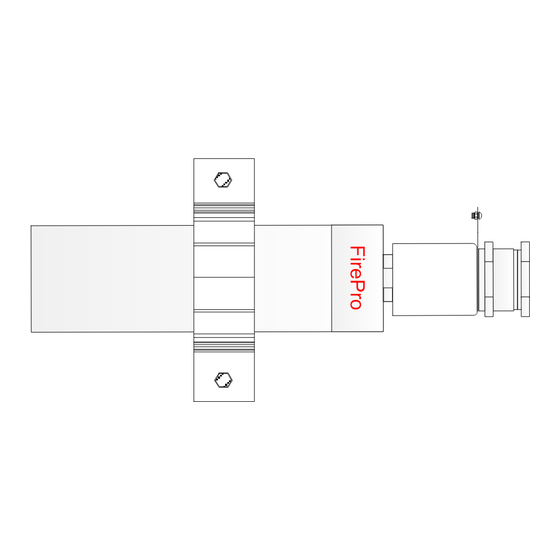
- Page 3 Aerosol Generator FP-20SE/T/TH Side View 32mm Diameter U-Type Metal Bottom View Bracket Step 1 Take the “Bracket” and place it on the aerosol generator. Step 2 Front View Align “Bracket” holes with surface material holes. Step 3 Select type of screws suitable to the surface material to be fixed (these screws are not supplied with the kit).
- Page 4 Select type of screws suitable to the surface material to be fixed (these screws are not supplied with the kit). Step 4 Pass the screws through the aligned holes and fix them on the surface material. FirePro Systems Step 5 REV. DESCRIPTION DATE The aerosol generator is ready for cable connections.
- Page 5 Select type of screws suitable to the surface material to be fixed (these screws are not supplied with the kit). Step 5 Pass the screws through the aligned holes and fix them on the surface material. FirePro Systems Step 6 REV. DESCRIPTION DATE The aerosol generator is ready for cable connections.
- Page 6 Select type of screws suitable to the surface material to be fixed (these screws are not supplied with the kit). Step 6 Pass the selected screws through the ( L ) bracket holes and fix them on the surface material. FirePro Systems Step 7 The aerosol generator is ready for cable connections. REV. DESCRIPTION...
- Page 7 Aerosol Generator FP-500S Step 1 Pass through the Aerosol Generator the 2 Ring Brackets FirePro Systems REV. DESCRIPTION DATE Generator Installation guide line 24/06/2016 Michaelides Loucas Page 6...
- Page 8 Step 2 Take each ( L ) bracket and place it inside the ( Ring ) bracket. Step 3 Align each ( L ) bracket holes to the ( Ring ) bracket holes. FirePro Systems REV. DESCRIPTION DATE Generator Installation guide line...
- Page 9 Step 4 Pass the screws through the aligned holes and tide them with the spanner key 11,13 to the nuts. Use screw size “M8” for the longer hole and screw size “M6” for the smaller hole. FirePro Systems REV. DESCRIPTION DATE...
- Page 10 Aerosol Generator FP-500S Step 5 Select type of screws suitable to the surface material to be fixed (these screws are not supplied with the kit). FirePro Systems REV. DESCRIPTION DATE Generator Installation guide line 24/06/2016 Michaelides Loucas Page 9...
- Page 11 Step 6 Pass the selected screws through the ( L ) bracket holes and fix them on the surface material. Step 7 The aerosol generator is ready for cable connections. FirePro Systems REV. DESCRIPTION DATE Generator Installation guide line 24/06/2016...
- Page 12 Guidelines about the wiring connections to the FirePro Aerosol Generators FP-20SE/T/TH, FP-40S/T, FP-80S/T,FP-100S, FP-200S,FP-500S. Step 1: Open the package and take one Aerosol Generator unit. Step 2: Disconnect the moving parts of the aerosol generator and separate the 3 units.
- Page 13 FP-20SE/T/TH, FP-40S/T, FP-80S/T,FP-100S, FP-200S,FP-500S. Cable gland fixing component UNIT 1 Cable gland & activator cable housing UNIT 2 2 X 1mm + Earthing wire Cut the cable and take out the earthing wire 3 cm 6.5 cm FirePro Generator 1.5 cm...
- Page 14 FP-20SE/T/TH, FP-40S/T, FP-80S/T,FP-100S, FP-200S,FP-500S. 2 X 1mm + Earthing wire 3 cm 6.5 cm 1.5 cm 4 mm Step 3.1 Step 3.2 Step 3.3 Step 3.4 Mark 3 cm from point (A) to point (B). Cut the positive wire ( + ) and negative Clean the positive wire ( + ) and Mark the cable 6.5cm from the edge...
- Page 15 FP-20SE/T/TH, FP-40S/T, FP-80S/T,FP-100S, FP-200S,FP-500S. Earthing wire Earthing wire Earthing wire Cable gland fixing component UNIT 1 Cable gland & activator cable housing UNIT 2 Pull back the cable until the edge of the cable shield just shown Activator cable housing...
- Page 16 FP-20SE/T/TH, FP-40S/T, FP-80S/T,FP-100S, FP-200S,FP-500S. Hold the cable Put Silicone Earthing wire Earthing wire Cable gland fixing Cable Spanner key # 22 component UNIT 1 Cable gland & activator Spanner key # 22 cable housing Put Silicone UNIT 2 Activator cable housing...
- Page 17 FP-20SE/T/TH, FP-40S/T, FP-80S/T,FP-100S, FP-200S,FP-500S. Earthing wire Earthing wire Silicone Silicone Cable gland fixing component UNIT 1 Earthing tag FirePro FirePro Step 11 Step 10 Seal with silicone the cut shielded Connect earthing wire with earthing cable and the entrance of the cable...
- Page 18 FP-20SE/T/TH, FP-40S/T, FP-80S/T,FP-100S, FP-200S,FP-500S. : Earthing wire DETAIL CABLE Earthing wire Earthing tag 2 X 1mm+ earthing wire Activator Cable Nikel plated M16 Housing Part 2 cable gland Activator Cable Cable connector Housing Part 1 Thermoconector Part 1 Manufacturer and world wide supplier FirePro Systems FirePro.
- Page 19 FirePro Systems 6 Koumandarias Street, PO Box 54080, CY-3720 Limassol, Cyprus - EU Tel.: +357 25 379999 | Fax: +357 25 354432 | Email: mail@firepro.com www.firepro.com...
Need help?
Do you have a question about the FP-20SE and is the answer not in the manual?
Questions and answers