
Related Manuals for FPS FSD Series


Summary of Contents for FPS FSD Series
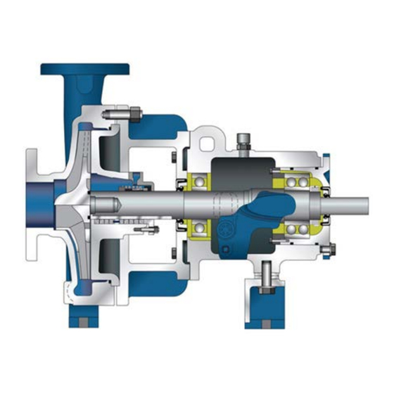
- Page 1 ENGLISH FSD SERIES ANSI Process Pumps Installation, Operation, and Maintenance Manual franklinwater.com...
-
Page 2: Table Of Contents
Table of Contents ....SAFETY CONSIDERATIONS ....PUMP IDENTIFICATION ....MANUFACTURER ....TYPE OF PUMP ....DATE OF MANUFACTURE ....INSTALLATION, OPERATION & MAINTENANCE MANUAL IDENTIFICATION ....WARRANTY ....GENERAL INSTRUCTIONS ....HANDLING AND TRANSPORT ....METHOD OF TRANSPORT ....SAFETY CONSIDERATIONS .... - Page 3 ....NEED FOR CLEANLINESS ....MAINTENANCE OF PUMP DUE TO FLOOD DAMAGE ....DISASSEMBLY ....FSD MODELS ....CLEANING/INSPECTION ....ASSEMBLY ....FSD POWER FRAME ASSEMBLY ....BEARING INSTALLATION ....FSD WET END ASSEMBLY ....BEARING LUBRICATION ....REINSTALLATION ....SPARE PARTS ....
-
Page 4: Safety Considerations
Maximum Lifting Speed: 15 feet/second. If in a climate where the fluid in the system could freeze, never leave The FSD Series ANSI Process pumps have been designed and manufac- liquid in the booster system. Drain the system completely. During tured for safe operation. -
Page 5: Pump Identification
PUMP IDENTIFICATION WARRANTY This product is covered by a Limited Warranty for a period of 12 MANUFACTURER months from the date of original purchase by the consumer. For complete warranty information, refer to www.franklinwater.com; or, Franklin Electric contact Technical Support for a printed copy. 125 Morrison Drive Rossville, TN 38066 Phone:... -
Page 6: Handling And Transport
Read and follow the storage instructions carefully because care of the HANDLING AND TRANSPORT pump during this period before installation can be as important as maintenance after operation has begun. METHOD OF TRANSPORT Check all parts against the packing list to make sure nothing is miss- The pump must be transported in the horizontal position ing. -
Page 7: Safety Considerations
SAFETY CONSIDERATIONS TEMPERATURES - °C TEMPERATURES - °C CD4M CD4M DINC 2000 2250 1750 2000 TEMPERATURE LIMIT 1500 DINC 1750 1250 1500 1000 CD4M UPPER LIMIT 1250 CR29 GROUP I & II DCI LOW TEMPERATURE CD4M 1000 CLASS 300 PUMPS LIMIT UPPER LIMIT BASED ON ANSI B16.5... - Page 8 MAXIMUM ALLOWABLE SUCTION PRESSURE - kPa 1750 2000 2250 2500 1000 1250 1500 Reverse vane impeller maximum allowable suction pressure 1750 RPM 3L6x8-14A 1L1.5x3-8 1L1.5x3-6 2L3x4-10H 1L2x3-6 2L2x3-8 2L3x4-8 2L3x4-10 2L1.5x3-10A 2L2x3-10A 2L4x6-10H 2L3x4-13HH 2L2x3-13 2L4x6-10 2L1.5x3-13 2L1x2-10A 1L1x1.5-6 1L1x1.5-8 2L4x6-13A 2L3x4-13 Suction Pressure is limited only by the pressure...
-
Page 9: Storage
STORAGE ing water plans), etc. are packaged and braced to withstand normal handling during shipment. In some cases compo- nents may be disassembled for shipment. The pump must be SHORT-TERM STORAGE stored in a covered, dry location. Normal packaging is designed to protect the pump during shipment It is recommended that the following procedure is taken: and for dry, indoor storage for up to two months or less. -
Page 10: Preparation
INSTALLATION & ALIGNMENT same condition as was the case at the factory. Thus the factory align- ment will be done with the base sitting in an unrestrained condition on a flat and level surface. This standard also emphasizes the need to PREPARATION ensure the shaft spacing is adequate to accept the specified coupling spacer. - Page 11 concrete foundation should be four (4) to six (6) times that mm) FIM angular. If this is not the case first check to see if of the pump, motor and base. Note that foundation bolts the driver mounting fasteners are centered in the driver feet are imbedded in the concrete inside a sleeve to allow some holes.
-
Page 12: Piping Connection - Suction & Discharge
Make sure that the grout fills the area under the base plate. have tapped holes, select flange fasteners with thread engagement at After the grout has cured, check for voids and repair them. least equal to the fastener diameter but that do not bottom out in the tapped holes before the joint is tight. -
Page 13: Suction Piping
Do not “spring” piping when making any connections. Provide for pipe expansion when hot fluids are to be pumped. DIAMETERS SUCTION PIPING When installing the suction piping, observe the following precautions. See FIGURE 6. The sizing and installation of the suction piping is extremely impor- SUCTION tant. -
Page 14: Discharge Piping
c. Where two or more pumps are connected to the same suc- Pump Insulation tion line, install gate valves so that any pump can be isolated from the line. Gate valves should be installed on the suction On chilled water applications most pumps are insulated. As part of side of all pumps with a positive pressure for maintenance this practice, the pump bearing housings should not be insulated since purposes. -
Page 15: Packing
Tap V Failure to ensure that packing is installed may result in serious leakage of the pumped fluid. PIPING CONNECTION – SEAL/PACKING SUPPORT SYSTEM FIGURE 7 - Packing Orientation Tap V If the pump has a seal support system, it is mandatory that this system be fully installed and operational before the pump is started. -
Page 16: Piping Connection - Support Leg Cooling For Centerline Mounting Option
PIPING CONNECTION – SUPPORT LEG PIPING CONNECTION – OIL MIST COOLING FOR CENTERLINE MOUNTING LUBRICATION SYSTEM OPTION The piping connections for an oil mist lubrication system are shown in FIGURES 12 & 13. If the casing is centerline mounted, and the process temperature is Locate Vent Fitting over 350°F (178°C), then the casing support legs may need to be 1/2”... -
Page 17: Coupling
COUPLING A direction arrow is cast on the casing. Make sure the motor rotates in the same direction before coupling the motor to the Pump. It is absolutely essential that the rotation of the motor be checked Excess grease is the most common cause of overheating. before connecting the shaft coupling. -
Page 18: Priming
PRIMING 60 Hz 50 Hz Minimum Minimum Pump Size If the pump is installed with a positive head on the suction, it can be Flow Flow primed by opening the suction and vent valve and allowing the liquid (% of BEP) (% of BEP) to enter the casing. -
Page 19: Operation In Sub-Freezing Conditions
2. A standard centrifugal pump will not move liquid unless 8. Surging Condition the pump is primed. A pump is said to be “primed” when A rapidly closing discharge valve can cause a damaging the casing and the suction piping are completely filled with pressure surge. - Page 20 POSSIBLE EFFECT PROBLEM Pump not primed/lack of prime/incomplete priming Loss of prime Suction lift too high Discharge head too high Rotational speed too low Incorrect direction of rotation Impeller plugged/impeller partially blocked by debris Air leak in suction line Air leak in discharge line Insufficient Net Positive Suction Pressure Available (NPSH Damaged impeller Defective packing...
- Page 21 POSSIBLE EFFECT PROBLEM Bearings worn Misalignment of pump and driver Defect in driver Voltage and/or frequency lower than previously thought Rotor assembly binding Rotational speed too high Foundation not rigid enough Lubrication grease and/or oil dirty & contaminated...
- Page 22 PROBLEM POSSIBLE CAUSE RECOMMENDED REMEDY Problem #1 Recalculate NPSH available. It must be Pump not reaching design flow rate. Insufficient NPSHA. (Noise may not be greater than the NPSH required by pump at present) desired flow. If not, redesign suction piping, holding number of elbows and number of planes to a minimum to avoid adverse flow rotation as it approaches the impeller.
- Page 23 PROBLEM POSSIBLE CAUSE RECOMMENDED REMEDY Cont. Problem #3.0 After confirming wrong rotation, reverse No discharge or flow Direction of rotation wrong. any two of three leads on a three phase mo- tor. The pump should be disassembled and inspected before operation. Air leak from atmosphere on suction side.
- Page 24 PROBLEM POSSIBLE CAUSE RECOMMENDED REMEDY Cont. Problem #6.0 When mounting the bearing on the out- Excessive noise from bearings. Brinelling of bearing identified by indenta- board end use a proper size ring and apply tion on the ball races, usually caused by the pressure against the inner ring only.
-
Page 25: Need For Maintenance Records
PROBLEM POSSIBLE CAUSE RECOMMENDED REMEDY Cont. Problem #6.0 1. Be sure the lubricant is clean. Excessive noise from bearings. Bearing damage due to improper lubri- 2. Be sure proper amount of lubricant is cation, identified by one or more of the used. - Page 26 (#372GM) and the stationary seat from the rear cover (#008). Once the rear cover (#008) has 4. Decontaminate the pump as necessary. If FPS pumps been removed, remove the stationary seat from the gland contain dangerous chemicals, it is important to follow plant (#372GM).
- Page 27 CLEANING/INSPECTION 17. Remove rear cover nuts (#544B) and carefully remove the rear cover (#008) from the power frame (#356). All parts should now be thoroughly cleaned and inspected. New bear- ings, O-rings, gaskets, and lip seals should be used. Any parts that 18.
- Page 28 The chart shown in FIGURE 22 gives the SKF part numbers for bearings stalled. The locknut should be torqued to the value shown in in FPS FSD pumps. Note that the term “inboard bearing” refers to FIGURE 21. At this point the lock washer tang must be bent the bearing nearest to the impeller.
- Page 29 FIGURE 21 – Shielded Bearing Arrangement The chart shown in FIGURE 22 gives the SKF part numbers for bearings in FPS FSD pumps. Note that the term “inboard bearing” refers to the bearing nearest to the casing. “Outboard bearing” refers to the bear- ing nearest to the motor.
- Page 30 Press Force Locknut Torque Pump lbf (N) ft•lbf (N•m) Group 1 1300 (5,780) 20 +5/-0 (27 +4/-0) Group 2 2500 (11,100) 0 +5/-0 (54 +7/-0) 4500 It must be understood that fixtures and equipment used to press the Group 3 70 +5/-0 (95 +7/-0) (20,000) bearing must be designed so no load is ever transmitted through the...
- Page 31 11. Install a new impeller gasket (#364). Place the shaft gland gasket (#364G) into the gland. sleeve (#756) onto the shaft (#728). 11. Install the rotating part of the mechanical seal (#372M) onto the shaft sleeve (#756) using a seal guide following the FSD WET END ASSEMBLY seal manufacturer’s instructions.
- Page 32 rings into the stuffing box. Now, attach the gland (#372GP) Minimum Maximum Oil to the rear cover (#008) using studs (#808G), nuts (#544G) Viscosity Viscosity Temperature and washers (#908G). Lightly snug up the gland (#372GP). Grade Index Final adjustments must be made after the pump has begun Up to 160°F (71°C) operation.
- Page 33 pipe plug from both the inboard and outboard bearing location. Housing Initial Lube Location lubrication Group 1 Inboard till grease comes out plug hole Group 1 Outboard till grease comes out plug hole 11 g Group 1 Duplex 30 g 15 g To re-grease bearings under coupling guard, stop pump, lock the mo- Group 2 Inboard...
- Page 34 And/Or HOW TO ORDER SPARE PARTS Topic Seal Provided Vendors By FPS Spare parts can be ordered from the local Franklin Electric Engineer in (mm) in (mm) or from the Franklin Electric Distributor or Representative. The pump Shaft size and type can be found on the name plate on the bearing housing.
- Page 35 (0.05 mm) (0.05 mm) Shaft Endplay The maximum amount of axial shaft movement, or endplay, on an FPS FIGURE 34 – Specialized Measurements pump should be 0.001 in (0.03 mm) and is measured as shown below. Observe indicator movement while tapping the shaft from each end in *The ASME standard recommends 0.005 in (0.13 mm) max deflection at...
- Page 36 The rotor revolves with the shaft, driven by a close FPS shafts do not exceed 16 µin (0.4 µm) at these areas. Franklin Electric fitted drive ring that rotates with the shaft. The stator is a stationary audits smoothness by using a profilometer surface finish gauge.
- Page 37 The VBXX is not intended to be separated from the bearing arm unless A. Position the outboard seal in the bore of the bear ing being replaced. arm (#86N & 86P) with the single expulsion port at the 6 o’clock position, (carefully keep aligned with the bore). 1.
- Page 38 7. From the oil level mark indicated on the equipment, use a level to put a mark on the outside of the Opto- Matic lower casting to indicate where the oil level should be (FIGURE 36D). Figure 36A 8. Measure the distance between Opto-Matic Oiler casting Direction of shaft rotation edge and top edge of spout angle (FIGURE 36E).
- Page 39 APPENDIX D INSTALLATION/CLEARANCE SETTING FOR REVERSE VANE IMPELLER Install the impeller (#444) by screwing it onto the shaft (use heavy gloves) until it firmly seats against the shaft shoulder. It is recommended that two people install a Group 3 impeller. The weight of a Group 3 impeller greatly increases the chance of thread damage and subsequent lock-up concerns.
- Page 40 At that point, the setting will be Like all front vane open style impellers, the FPS semi-open impel- 0.018 in (0.46 mm). Tightening the set screws will cause a 0.002 in (0.05 mm) draw of ler clearance must be set off the casing.
- Page 41 is simply set off the rear cover by the same distance recorded earlier. Note that if the casing, cover, impeller or shaft need to be replaced this shortcut method will not work. APPENDIX F REMOVAL/INSTALLATION OF SEALS WITH FMI SEAL CHAMBER REMOVAL After removing the impeller, slide the hook sleeve off the shaft.
- Page 42 APPENDIX G ALLOWABLE NOZZLE LOADS FSD PUMPS (ASME B73.1M) The allowable nozzle loads listed in Figure 52 may be applied to any The loads listed in FIGURE 42 are the combined values resolved to FSD Standard Horizontal and Lo-Flo pumps in Ductile cast iron, Carbon the center of the pump, except for the Fr + Mr/3 limits, which apply Steel, 316 Stainless Steel, Cd4MCu, Monel, and Inconel.
- Page 43 Combined Loading at Center of Pump Pump Loading Flange Suction Nozzle Forces (N) Moments (N•m) Discharge Frs+Mrs*1.098 Sizes Frd+Mrd*1.03 1 x 1.5 1313 1046 1446 1.5 x 1.5 1313 1046 1446 1446 1 x 2 1624 1268 1936 1.5 x 2 1802 1446 1108...
- Page 44 472B 708B 364N 544N 708N 069N 069P 364P 372GM 364G 544A 372M 808A 364A 008 179 444 164N 364B 708F 676S 544G 372GP 544B 808G 676L 372P 808B FIGURE 45 FSD ANSI PUMP ITEM DESCRIPTION ITEM DESCRIPTION ITEM DESCRIPTION REAR COVER 372P PACKING SHAFT SLEEVE...
- Page 45 472B 708B 364N 544N 708N 069N 356 995 676P 069P 364P 372GM 364G 544A 372M 808A 364A 008 179 444 364 164N 364B 676S 708F 372GP 676L 372P 364C 708A 544B 544G 544B 808B FIGURE 46 FSD ANSI PUMP ITEM DESCRIPTION ITEM DESCRIPTION...
- Page 46 472B 364N 708B 544N 708N 069N 676P 995 356 069P 364P 028 372GM 544A 364G 808A 364A 372M 008 179 444 364 164N 364B 164A 708F 676S 364C 708A 544G 544B 372GP 808G 676L 372P FIGURE 47 808B FSD ANSI PUMP ITEM DESCRIPTION ITEM...
- Page 47 NOTES...
- Page 48 For technical assistance, parts, or repair, please contact: 901.850.5115 | franklinwater.com Form 10000002024 Rev. 000 06/20 Copyright © 2020, Franklin Electric, Co., Inc. All rights reserved.
Need help?
Do you have a question about the FSD Series and is the answer not in the manual?
Questions and answers