
Related Manuals for AEA Technology, Inc. Bravo MRI II


Summary of Contents for AEA Technology, Inc. Bravo MRI II
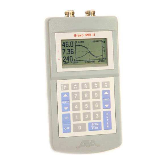
- Page 1 Dual Port Vector Impedance Analyzer rt Vector Impedance Analyzer – 100KHz to 200 MHz...
- Page 2 AEA Technology, Inc. is copyrighted and may not be copied or altered in any way without the written consent from AEA Technology, Inc. written consent from AEA Technology, Inc. VIA Bravo MRI II , Bravo PC Vision and AEA Logos are trademarks of AEA Technology, Inc. 1998 and AEA Logos are trademarks of AEA Technology, Inc.
-
Page 3: Table Of Contents
Table of Contents INTRODUCTION ........................1 MRI II H ............. 1 RAVO IGHLIGHTS .............. 1 SING ANUAL QUICK START ........................2 OPERATING THE BRAVO MRI II UNIT ................3 ............. 3 ENTER REQUENCY ............... 3 WEEP ANDWIDTH ............4 REQUENCY ................5 ................ - Page 4 3.12.4 Numeric Quantities ....................13 3.12.5 80 Point Sweeps....................13 3.12.6 100 Point Sweeps....................13 APPLICATIONS AND MEASUREMENT EXAMPLES ............14 ½ ........14 AKE A WAVELENGTH COAXIAL LINE ¼ ........14 AKE A WAVELENGTH COAXIAL LINE ........15 OUPLES INTO OWER ........
-
Page 5: Introduction
You can choose to display the impedance from among several formats. The Bravo MRI II sweeps across a range of frequencies, or operates at CW, either way the display is continuously updated with new measurement results. This unit has many applications, including: 1. -
Page 6: Quick Start
The next time you power up, these settings will reload, putting the Bravo MRI II in the same state that you last used it in. If you ever want to start the Bravo MRI II with factory preset values, hold the ENTER key while you power up the unit, otherwise, the unit will load up the settings that were in effect the last time the OFF key was pressed.. -
Page 7: Operating The Bravo Mri Ii Unit
ENTER enough times to push through the menus without altering the settings Whenever you are in a menu, the Bravo MRI II lists your choices for keypad entries to help you make your choice and return to measuring. -
Page 8: Frequency Step Size
MRI II adjusts your entry to an available sweep width. For example if you enter a 1.000 MHz wide sweep, the Bravo MRI II sets the sweep width to 1.000 MHz if the unit is plotting 100 points, but will set the sweep width to a 1.600 MHz if the graph is set to 80 points. The Bravo MRI II flashes a brief warning if it changes the sweep width from the number you entered. -
Page 9: Exam/Plot
The unit is configured with the settings that were in effect when the OFF key was last pressed. If you ever want to start the Bravo MRI II with factory preset values, hold the ENTER key while you power up the unit. -
Page 10: F2 Instrument Properties (Adjustments And Settings)
10 sweeps after returning to measuring. Also note the maximum intensity is limited and the backlight will only be noticed in dim light conditions. When the Bravo MRI II is in a bright environment, the backlight will be washed out. -
Page 11: Cable Nulling
The Bravo MRI II can graph up to two plots on the display. More plots may be displayed if you connect the Bravo MRI II to a PC running the VIA-RTD software. In addition to the two plots, some information is also displayed numerically. When the plotting width is 100 points, all of the center frequency data is displayed with small digits. -
Page 12: Right Plot Data
3.9.1.1.5 R.C. Mag (Reflection Coefficient Magnitude) This is the magnitude of the S11 vector. Minimum value is zero and implies perfect match. Maximum value is 1.0, complete reflection of energy. 3.9.1.1.6 R.C. Angle (Reflection Coefficient Angle) This is the same thing as the phase angle of the S11 vector. This angle contains the information to determine cable length. -
Page 13: Rlc Model Series/Parallel
3.9.3 RLC Model Series/Parallel The equivalent L or C (calculated from the reactance at the center frequency) can be displayed numerically. The equivalent load appears as a resistor and a capacitor (or resistor and inductor). The values of the resistance and reactive component can be calculated as two components in series or two components in parallel. -
Page 14: Right Plot Scale
3.10.4 Right Plot Scale Select the scale of the right plot. Choices vary depending on what is being plotted. 3.11 F5 Memory and Miscellaneous This menu lets you save and recall data, set the plot name, set the cable properties, set the baud rate, and perform a self test. -
Page 15: Com Port Baud
3.11.5 Com Port Baud You can set the bit rate you wish to use in this sub menu. The data format is always N-8- 1 with XON/XOFF handshaking. 3.11.6 Self Test You can perform a self test by selecting this choice. Press ENTER to quit the self test. Pressing any other key creates a response that indicates the key is operating. -
Page 16: Cable Nulling Using The Included Terminators
(see Error! Reference source not found.or Error! Reference source not found.). Install the cable to be nulled to the RF connector of the Bravo MRI II unit. Once the instrument mode is selected and the cable is connected, the procedure can begin using the included terminators. -
Page 17: Calibration Cycles
3.12.3 Calibration Cycles The Bravo MRI II MRI will periodically enter a calibration cycle. This ensures the best accuracy over long periods of time. Changing certain sweep parameters can also induce a calibration cycle. Sometimes you may want to enter something into the keypad while a calibration cycle is in progress. -
Page 18: Applications And Measurement Examples
2. Connect one end of coax to Bravo MRI II (preferably using a coaxial connector), the other end is left open. Set the Bravo MRI II center frequency to the desired ½ wave frequency. There should be an impedance peak (and a zero phase crossing) slightly to the left of the center frequency. -
Page 19: Load Couples Into Power Line
When this occurs, the plot lines may be “thicker” and the readings will shift around a lot. There are two methods to eliminate this effect 1. Power the Bravo MRI II from batteries. The wall power pack must be unplugged from the Bravo MRI II power jack to do this. -
Page 20: Operation With The Via-Rtd Software
The VIA-RTD software has its own manual on the CD. This manual is loaded to the hard drive when you install the program on your computer. Connect the Bravo MRI II to the PC with an AEA serial cable (PN 0070-1201) or extra long cable(PN0070-1215). Be sure that the bit rate of the serial port matches the setting selected on the Bravo MRI II unit. -
Page 21: Care And Maintenance
RF or a Magnetic Field. Do not connect the VIA Bravo MRI II to an active transmitter. The VIA Bravo MRI II Should Not be allowed to get closer than 3 feet (1 meter) with a 1.5T Coil , and 5 feet (1.5 meter) with a 3T Coil Before attaching the Bravo MRI II to an antenna, it's a good practice to briefly ground the feed line in order to allow any accumulated static charge(s) to dissipate. -
Page 22: Limited Warranty
7 Limited Warranty AEA Technology, Inc., warrants to the original purchaser that the Bravo MRI II Analyzer shall be free from defects in material or workmanship for a period of one year from the date of shipment. All units returned to the factory, delivery charges prepaid, and deemed defective under this warranty, will be replaced or repaired at this company’s option. -
Page 23: In Case Of Trouble
8 In Case of Trouble Some problems may be identified and solved by the operator. More involved problems will require factory service. To try to solve a problem yourself, refer to the chart below: Symptom Possible cause Refer to paragraph On power up, I hear Display contrast setting 3.8.2, 8.1, 8.1.2... -
Page 24: Power Induced Failure
8.2 Batteries Install a fresh set of "AA" batteries; or (if possible) observe the operation of the Bravo MRI II while switching back and forth between battery power and and external DC supply (refer to Section 0). 8.3 Serial Port Ensure that your cabling and communication software is configured in accordance with the specification in Section 9.1.4.2. -
Page 25: Other Problems
8.4 Other Problems If you have any questions concerning instrument maintenance, cleaning, care, or before making any return, warranty or out-of-warranty for an operational issue, material defect, or routine calibration, please contact AEA Technology first. Our trained staff can and do resolve most issues and get our customers operating again over the phone or by email. -
Page 26: Appendices
9 Appendices 9.1 Bravo MRI II Specifications 9.1.1 Output Characteristics 9.1.1.1 Frequency Range From 100 KHz to 200MHz 9.1.1.2 Sweep Width Min: Less than +/- 1.0% of center frequency Max: 25.6MHz or 32 MHz (for 80 or 100 point graphs) For center frequencies >51.6MHz (80 points) or 64.4MHz (100 points) the... -
Page 27: Display Characteristics
9.1.2.2 Impedance Formats 9.1.2.2.1 S11 Measurements Total Z, Z angle, Resistance, Reactance, SWR, Return loss, Reflection Coefficient (RC) magnitude, RC angle 9.1.2.2.2 S21 Measurements Linear Gain, Gain angle, Logarithmic Gain 9.1.2.3 Accuracy 9.1.2.3.1 Impedance The accuracy varies as a function of the load. +/- 1 ohm at 10 ohm load +/- 1.5 ohms at 50 ohm load +/- 4 ohm at 100 ohm load... -
Page 28: Miscellaneous Specifications
Data type 8 bit, no parity, and 1 stop bit, with XON/XOFF handshake 9.1.4.2.3 Connector type Serial input is a 1/8 inch stereo jack. Tip = RD (from Bravo MRI II to PC), Ring = TD (from PC to Bravo MRI II), Common=ground... -
Page 29: Battery Power (Choice Of:)
9.1.4.3 Power Requirements The Bravo MRI II may be battery or wall powered. Use of the AEA wall power pack (PN 5001-0201) is recommended when using wall power. 9.1.4.3.1 DC input (Power jack) Min 10 VDC (450 ma) Typical 14VDC (250ma) Max 20VDC (250 ma) 2.1 mm center pin DC power connector. -
Page 30: Menu Chart
9.2 Menu Chart 9.2.1 Function Key Operations Function Key 1st level menu 2nd level menu 3rd level menu F1 Help Page Off, 10, 20, 50 sweeps, Backlight or continuous, plus 16 Control brightness levels Display Contrast 16 levels Unit Properties 4 Volume levels plus 3 Audio Options modes: on, off, readout Cable Nulling... -
Page 31: Non Function Key Operations
SWR scales: 3, 6, 11 Return Loss scales: 20, 50, 90 dB S11 mag scales: same choices as Z, S11 angle scales: same choices as Z angle plus +/- 180 Save Enter 1 to 24 Enter memory name Recall Enter 1 to 24 Alpha-numeric entry up Plot Name to 12 chars... -
Page 32: Serial Port Command And Control
Some commands do not require the EOS marker. The Bravo MRI II unit sends an EOS marker in response to a command. If the Bravo MRI II doesn’t understand the command, no EOS response occurs. The ASCII char ‘*’ (ASCII 0x2a) is used as the EOS marker. - Page 33 9.3.1.1.3 D Send the distance reading in millimeters. This command only operates when the Bravo MRI II unit is in the cable analyzer mode. . No EOS marker is required, but one may be sent if desired. 9.3.1.1.4 Mxx Read the data stored in memory location xx. The EEPROM memory location contains the unit setup info, and sometimes the plot from a single sweep saved by the user.
- Page 34 Measured Data Header Table Characters Meaning Notes Range of Sent x...x These numbers depend on Fx…x 100,000 to Center frequency in the version 200,000,000 Max width depends on plot Wx…x 0 to Sweep width in Hz width of 80 or 100 points 51.2MHz or 64MHz Data sent in pairs (Z,A or...
-
Page 35: Unit Setup
Memmax. 9.3.2 Unit Setup There are several pieces of information that can configure the Bravo MRI II unit. Information such as sweep width, center frequency and data format can be altered individually. Other setup information must be sent in a block of data that contains the entire setup information for the unit. - Page 36 9.3.2.1 Unit Setup commands 9.3.2.1.1 Fx..x Set the center frequency, x..x is the center frequency in Hz. Range of center frequencies depends on version of unit, limits can be determined from unit setup data. No EOS marker is required if immediately followed with another command, but one may be sent if desired. If this is the last command in a string, the EOS marker must be used.
- Page 37 Setup Data Table Characters Range of x…x Meaning Notes Received S002 Toss this out Header denotes unit setup info follows Fx…x 100,000 to Center frequency in 200,000,000 Wx…x 0 to 51.2MHz or Sweep width in Hz 64MHz Dxxx 101 to 104 Data format Overrides plot type if in conflict.
- Page 38 future use Ax…x 0 to 15 Right plot type See left above 0=+/- dF; 1= +/- F Ax…x 0 to 1 X axis Label 0=open; 1=short Ax…x 0 to 1 Cable test mode Ax…x 0 to 2,000 , characteristic Z cable Z Cable Vf Ax…x...
-
Page 39: Examples
Read Save memory 1, Freq=200K, …A50000* Width=4KHz, Instrument mode = VIA; Memory slots = 24, … Max center freq=50MHz S000 S002F500000W32000A1A5…A2 Bravo MRI II’s current settings: 00000* Freq=500K, Width=32KHz, Instrument mode = SWR; Freq step=5KHz, … Max center freq=200MHz F5000000*... -
Page 40: Ascii Table
9.4 ASCII Table 0 Null Space " & XOFF < > Characters 0 to 31 are not used by Bravo MRI II except for XON/XOFF Lower case letters are not used by Bravo MRI II... -
Page 41: Coaxial Cable Reference Table
9.5 Coaxial Cable Reference Table Coax Part # Characteristic Z Velocity factor % 10base2 9907 10base5 9880 FSJ150A FSJ1-75 FSJ4-50B FSJ4-75A FT4-50 HJ4-50 HT4-50 HJ4.5-50 HJ5-50 HT5-50 HJ5-75 HJ7-50 HJ8-50 HJ9-50 HJ11-50 HJ12-50 LDF2-50 LDF4-50 LDF4-75 RG-6/U 9116 RG-6A/U 8215 RG-8/U 8214 RG-8/U 8237 RG-8/U 9913... - Page 42 RG-62 9862 RG-62A/U 9269 RG-58B/U 825 RG-63 9857 RG-71 9169 RG-122/U 9252 RG-141A/U RG-142 RG-142B/U RG-174/U 8216 RG-178B/U RG-179 83264 RG-180 83266 RG-187A/U RG-188A/U RG-212/U 9861 RG-213/U 8267 RG-214/U 8268 RG-216 9850 RG-223/U 9273 RG-303 84303 RG-316 84316 RG-316/U 83284 RG-402/U 1673A RG-405/U 1671A...
- Page 43 Example #1 This shows the effectiveness of the Noise Filter. Be aware that the filter will smooth almost any curve and may alter good data. A perfectly good Return Loss plot has a very sharp point at the bottom without the filter on. Applying the filter will drastically change this sharp point.
- Page 44 Notes:...
- Page 45 5933 Sea Lion Place Suite 112 Carlsbad CA 92010 Tel: 800 Tel: 800-258-7805 or +1-760-931-8979 Fax: +1-760-931-8969 www.aeatechnology.com...
Need help?
Do you have a question about the Bravo MRI II and is the answer not in the manual?
Questions and answers