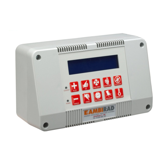
Summary of Contents for Ambirad Smartcom 3
- Page 2 1 Single Zone System. SmartCom Mulitizone 1/L 2/N LIVE S/R0S/R1 D0 D1 O0 O1 B1 B0 B2 C2 C0 C1 66 64 20 NEUT Black Bulb Sensor Outside 40VA Sensor Trans (where applicable) S-0700 Relay eg E.M.S. L1 (HOT) 120V 60Hz 1 Ph 20 amp Supply S-0755 Relay...
- Page 3 NOTES: To other slave SmartCom Mulitizone NETWORK. Master-slave (Network) controllers Burners (Slave 1) communication is by shielded twisted pair cable, RS485 Zone B compatible such as Belden 9841. Maximum overall system length of 1650ft Connect screen to C0. NOTE: Diagram shows a master and ONE slave configuration**.
- Page 4 To other slave NOTES: SmartCom Mulitizone controllers Burners (Slave 1) NETWORK. Master-slave (Network) Zone B communication is by shielded twisted pair cable, RS485 compatible such as Belden 9841. Maximum overall system length of 1650ft Connect screen to C0. NOTE: Diagram shows a master and ONE slave configuration**.
- Page 5 4 Single Zone System c/w Motorised Damper. SmartCom Mulitizone 1/L 2/N LIVE S/R0 S/R1 D0 D1 O0 O1 B1 B0 B2 C2 C0 C1 66 64 20 NEUT Black Bulb Sensor Outside Sensor (where applicable) 40VA Trans L1 (HOT) 120V 60Hz 1 Ph 20 amp Supply eg E.M.S.
- Page 6 NOTES: To other slave SmartCom Mulitizone NETWORK. Master-slave (Network) controllers Burners (Slave 1) communication is by shielded twisted pair cable, RS485 Zone B compatible such as Belden 9841. Maximum overall system length of 1650ft Connect screen to C0. NOTE: Diagram shows a master and ONE slave configuration**.
- Page 7 NOTES: To other slave SmartCom Mulitizone NETWORK. Master-slave (Network) communication is by controllers Burners (Slave 1) shielded twisted pair cable, RS485 compatible such as Zone B Belden 9841. Maximum overall system length of 1650ft Connect screen to C0. NOTE: Diagram shows a master and ONE slave configuration**.
- Page 8 Burners NOTES: Zone B SmartCom Mulitizone To other slave NETWORK. Master-slave (Network) (Slave 1) controllers communication is by shielded twisted pair cable, RS485 compatible such as Belden 9841. Maximum overall system length of 1650ft Connect screen to C0. NOTE: Diagram shows a master and ONE slave configuration**.
- Page 9 8 Single Zone System 3Phase. SmartCom Mulitizone 1/L 2/N LIVE S/R0 S/R1 D0 D1 O0 O1 B1 B0 B2 C2 C0 C1 66 64 20 NEUT Black Bulb Sensor 40VA Trans 120V 60Hz 1 Ph Outside 20 amp Supply Sensor (where applicable) S-0700 Relay...
- Page 10 9 Single Zone System via Inverter 3Phase. SmartCom Mulitizone 1/L 2/N 10 LIVE S/R0S/R1 D0 D1 O0 O1 B1 B0 B2 C2 C0 C1 66 64 20 NEUT Black Bulb Sensor Outside 40VA 120V 60Hz 1 Ph Sensor Trans 20 amp Supply (where applicable) S-0700 Relay...
- Page 11 NOTES: To other slave NETWORK. Master-slave (Network) SmartCom Mulitizone controllers Burners communication is by shielded (Slave 1) twisted pair cable, RS485 Zone B compatible such as Belden 9841. Maximum overall system length of 1650ft Connect screen to C0. NOTE: Diagram shows a master and ONE slave configuration**.
- Page 12 NOTES: To other slave NETWORK. Master-slave (Network) SmartCom Mulitizone controllers Burners communication is by shielded twisted (Slave 1) pair cable, RS485 compatible such Zone B as Belden 9841. Maximum overall system length of 1650ft Connect screen to C0. NOTE: Diagram shows a master and ONE slave configuration**.
- Page 13 Isolator End Vent End Vent Burner Module Isolator Branch Zone 2 In-line Burner Sensor Zone 2 18 Awg In-line Burner Shielded Isolator Cable Isolator 2nd Branch Zone 1 115V 60Hz In-line Burner In-line Burner Mains Supply Isolator Isolator SmartCom³ no.2 Tail Pipe 'SLAVE' (SC3-MZ) 1st Branch Zone 1...
- Page 14 13 Modulation Damper and Pressure Switches DAMPER CONNECTIONS The fan damper is wired via a plug and socket FIXED CONNECTION arrangement. The socket is connected to the assembly via a bracket. Release the loose plug and remove the cap via two ON PLUG screws.
- Page 15 (17mm) End Vent L104102 L104101 L104100 L104103 Orifice Plate (16mm) (24mm) (27mm) (28mm) End Vent Suction (All Models) Minimum Fire 0.5” to 1” WG Maximum Fire 2.5” to 3” WG Please contact an AmbiRad representative for installations over 4000’ elevation...
- Page 16 15 SmartCom³ ARC Commissioning. For ease and swiftness of initial start-up, the immediately with standard Infrared Radiant SmartCom³ range of electronic controllers is heaters. supXXplied factory pre-set to default settings as described in the SmartCom³ Installation and To alter the control system to a single or User Manual ref US/SCOM/29.
- Page 17 Notes: Remote Door Interlock MASTER & SLAVE (NETWORK) EXT ERNAL / DOOR F ROST ONL Y When setting up a SmartCom³ Master and Slave (Network) system, the master controller will display error message during SmartCom³ controllers can be connect to a commissioning.


Need help?
Do you have a question about the Smartcom 3 and is the answer not in the manual?
Questions and answers