MIR 500 User Manual
Hide thumbs
Also See for 500:
- User manual (219 pages) ,
- Quick start manual (48 pages) ,
- Operating manual (36 pages)
Table of Contents
Advertisement
Advertisement
Table of Contents

Related Manuals for MIR 500


Summary of Contents for MIR 500
- Page 1 User guide (en) Date: 06/2020 Revision: v.1.4...
- Page 2 All rights reserved. No parts of this manual may be reproduced in any form without the express written permission of Mobile Industrial Robots A/S (MiR). MiR makes no warranties, express or implied, in respect of this document or its contents. In addition, the contents of the document are subject to change without prior notice.
-
Page 3: Table Of Contents
Table of contents 1. About this document 1.1 Where to find more information 1.2 Version history 2. Safety 2.1 Safety message types 2.2 General safety precautions 2.3 Intended use 2.4 Users 2.5 Foreseeable misuse 2.6 Risk assessment 2.7 Residual risks 2.8 Safety-related functions and interfaces 2.9 Limiting safety-related functions 2.10 Safety-related electrical interfaces... - Page 4 4.2 Connecting to the robot interface 4.3 Driving the robot in Manual mode 4.4 Checking the hardware status 4.5 Charging the robot 4.6 Shutting down the robot 4.7 Creating and configuring a map 5. Planning 5.1 Analysis of the work environment 5.2 MiR500 user roles 5.3 Creating an efficient map 5.4 Creating efficient missions...
- Page 5 7. Applications 7.1 Mounting a top module 7.2 Lift modifications 8. Maintenance 8.1 Regular weekly checks and maintenance tasks 8.2 Regular checks and replacements 8.3 Packing for transportation 9. Payload specifications 10. Interface specifications 10.1 General purpose interfaces 10.2 Safety interfaces 10.3 Connector list MiR500 User guide (en) 06/2020 - v.1.4 ©Copyright 2018-2020: Mobile Industrial Robots A/S.
-
Page 6: About This Document
The following resources are available: • Quick starts describe how you start operating MiR robots quickly. This document is in print in the box with the robots. Quick starts are available in multiple languages. • User guides provide all the information you need to operate and maintain MiR robots. -
Page 7: Version History
1. About this document • The MiR network and WiFi guide specifies the performance requirements of your network and how you must configure it for MiR robots and MiR Fleet to operate successfully. 1.2 Version history This table shows current and previous versions of this document and their interrelations with hardware releases. -
Page 8: Safety
2. Safety 2. Safety Read the information in this section before powering up and operating MiR500. Pay particular attention to the safety instructions and warnings. NOTICE Mobile Industrial Robots disclaims any and all liability if MiR500 or its accessories are damaged, changed, or modified in any way. Mobile Industrial Robots cannot be held responsible for any damages caused to MiR500, accessories, or any other equipment due to programming errors or malfunctioning of MiR500. -
Page 9: General Safety Precautions
2. Safety 2.2 General safety precautions This section contains general safety precautions. WARNING Using a charger different from the one supplied by the manufacturer can cause a fire. • Use only the original charger. WARNING Lithium battery packs may get hot, explode or ignite and cause serious injury if they are abused electrically or mechanically. -
Page 10: Intended Use
MiR500. MiR500 is designed and all risks are considered when used with one of the following types of top applications: • MiR500 Pallet Lift used with MiR Lift Pallet Rack. • MiR500 EU Pallet Lift used with MiR EU Pallet Rack. •... -
Page 11: Users
Operators Operators have thorough knowledge of MiR500 and of the safety precautions presented in the user guide of MiR Fleet PCMiR500 and operating guide of MiR500. Operators have the following main tasks: MiR500 User guide (en) 06/2020 - v.1.4 ©Copyright 2018-2020: Mobile Industrial Robots A/S. -
Page 12: Foreseeable Misuse
• Using MiR500 to transport people • Using MiR500 on steep surface grades, such as ramps • Exceeding the total payload of 500 kg • Positioning or fastening load incorrectly according to the specifications See the Payload specifications on page 90 •... -
Page 13: Residual Risks
MiR does not take any responsibility for the creation of the risk assessment, but we provide information and guidelines that may be used in the MiR 500 and MiR1000 Risk Analysis Guide found on the Distributor Site under Manuals. -
Page 14: Limiting Safety-Related Functions
2. Safety 2.9 Limiting safety-related functions MiR500 has several built-in safety-related functions that are used to ensure safe operation in the environment it is designed to be used in. Advanced control software ensures that locomotion and the drive pattern are within safety related limits and thereby avoid triggering a safety function. -
Page 15: Safety-Related Electrical Interfaces
2. Safety Overspeed avoidance The safety system monitors if the speed of each motor is above limits for maximum rated speed and hence an indication of speed control is lost for any reason. The overspeed avoidance safety function must be manually deactivated by activation of the restart button. - Page 16 2. Safety System emergency stop input This input should be used in case a top manipulator has its own emergency stop circuit. The input must be used in combination with a system emergency stop output. With this, it is possible to ensure that activation of any emergency stop button will cause an emergency stop of both MiR500 and top manipulator.
-
Page 17: Lithium Battery
2.11 Lithium battery This section contains safety precautions related to lithium batteries in MiR robots. NOTICE MiR does not support any additional batteries applied to the MiR500 by the customer. WARNING Lithium battery packs may get hot, explode or ignite and cause serious injury if they are abused electrically or mechanically. -
Page 18: Getting Started
MiR500 document folder containing the printed documents and the USB flash drive. Printed documents: • MiR500 Quick Start • MiR username and passwords • CE declaration of conformity MiR500 User guide (en) 06/2020 - v.1.4 ©Copyright 2018-2020: Mobile Industrial Robots A/S. -
Page 19: Unpacking Mir500
3. Getting started USB flash drive with the following content: • MiR500 User Guide • MiR Robot Interface 2.0 Reference guide • MiR robot REST API reference • MiR Charge 48V Operating Guide • MiR500 Pallet Lift Operating Guide • MiR500 EU Pallet Lift Operating Guide •... - Page 20 3. Getting started Remove the lid from the box. Take the folder with the printed documents and the USB drive out of the box. Remove the walls of the box and the protective foam blocks. MiR500 User guide (en) 06/2020 - v.1.4 ©Copyright 2018-2020: Mobile Industrial Robots A/S.
- Page 21 3. Getting started Cut the protective straps. Place the lid of the box so that you can use it as a ramp. Align the lid so that it is flush with the base of the box. MiR500 User guide (en) 06/2020 - v.1.4 ©Copyright 2018-2020: Mobile Industrial Robots A/S.
- Page 22 3. Getting started Remove the wheel stop board from the pallet to let the robot drive on the ramp. MiR500 User guide (en) 06/2020 - v.1.4 ©Copyright 2018-2020: Mobile Industrial Robots A/S.
-
Page 23: Security
MiR500 communicates all data over the network that it is connected to. It is the responsibility of the commissioner to ensure that it is connected to a secure network. MiR recommends creating an IT-security risk assessment before commissioning the robot. - Page 24 3. IT security Understanding MiR software versions MiR uses the Major.Minor.Patch.Hot fix format to version our software. For example, 2.8.1.1 means that the software is based on the second major release, the eighth minor release of the major version, the first patch release of the minor version, and in this example a single hot fix is included too.
-
Page 25: Commissioning
4. Commissioning 4. Commissioning This section describes how to get started with MiR500. 4.1 Powering up Follow these steps to power up MiR500. Open the rear maintenance hatch. To open the hatch, push two buttons on the hatch and pull the hatch. Turn the battery disconnect switch to position ON. - Page 26 4. Commissioning Ensure that all four emergency stop buttons are in the released state. Turn an emergency stop button clockwise to release it. Press the On/Off button for five seconds. The robot turns on the red indicator lights and starts the software initialization process. When the initialization process ends, the robot goes into the emergency stop mode.
-
Page 27: Connecting To The Robot Interface
NOTICE The username and password for the robot’s WiFi access point and for accessing the web interface are in the MiR username and passwords document. The document is in the box with the robot. Follow these steps to connect to the robot interface: Using your pc, tablet or phone, connect the WiFi access point of the robot. -
Page 28: Driving The Robot In Manual Mode
4. Commissioning In a browser, go to the address mir.com and sign in. Switch to manual mode, and drive the robot down the ramp, see section Driving the robot in Manual mode below. 4.3 Driving the robot in Manual mode To drive the robot in Manual mode: Put the Operating mode key into the Manual mode (turn to the right). - Page 29 4. Commissioning Press the Restart button. The status lights turn blue indicating that the robot is in Manual mode. The robot is shown with an EU pallet lift. MiR500 User guide (en) 06/2020 - v.1.4 ©Copyright 2018-2020: Mobile Industrial Robots A/S.
-
Page 30: Checking The Hardware Status
4. Commissioning Drive the robot using the joystick. 4.4 Checking the hardware status To check that all hardware components work as intended follow the steps below: Sign in to the robot interface. See the section Connecting to the robot interface on page 27. -
Page 31: Charging The Robot
Check that all elements on the page have the OK status and that they have green dots on the left. For more information, see Hardware health in MiR Robot Interface Reference Guide. 4.5 Charging the robot A charger cable and an external charger is not part of the MiR500 standard delivery. - Page 32 4. Commissioning Connect the charger cable to the charging connector on the robot. For information about the charging time, see the robot specifications at www.mobile- industrial-robots.com. MiR500 User guide (en) 06/2020 - v.1.4 ©Copyright 2018-2020: Mobile Industrial Robots A/S.
-
Page 33: Shutting Down The Robot
4.7 Creating and configuring a map The robot requires a map to operate. For information about creating a map, refer to MiR Robot Interface Reference Guide. Section Creating an efficient map on page 39 describes how to make the map efficient and how to mitigate potential risks. -
Page 34: Planning
The correct setup and thorough training of the users will result in a successful and safe installation of MiR500. For more details on the topics below, refer to the MiR Robot Interface Reference Guide. NOTICE Read section Safety on page 8 before going through this chapter. - Page 35 5. Planning • Emergency stop: the laser scanners trigger the emergency stop as part of the SICK Safety system when an obstacle is within the emergency zone of the laser scanners. • Mapping: the laser scanners record the environment to gather data that enable the creation of a map.
-
Page 36: Mir500 User Roles
5. Planning Laser scanners of the robot will only detect parts of the chair. Here, the scanners detect the four legs of the chair in the upper left corner of the map. The 3D camera will detect more details of the chair when it is close enough to it. 5.2 MiR500 user roles Introducing MiR500 into the company will require some changes to the environment and the people working with the robot to achieve the optimal benefits. - Page 37 5. Planning • Working directly with MiR500. • Working indirectly with MiR500. • Responsible for MiR500. Direct user The direct user of MiR500 could be someone who commands the robot to carry out missions and works closely with the robot. Apart from training on how to use the robot (see Training of the users on the next page), the direct user will need to make adjustments to his/her work...
- Page 38 • What functions or widgets should be available for the different users? For more details on interface and dashboards, see MiR Robot Interface Reference Guide. Training of the users It is very important to spend time on training the different users of MiR500. It is unlikely that all users will need to know all the features of the robot.
-
Page 39: Creating An Efficient Map
A good map is also the basis for a safe and efficient robot. If you have not created a map before, see MiR Robot Interface Reference Guide and How-to guides on our Distributor website. - Page 40 5. Planning Use zones on the map Adding zones to the map can organize efficient robot traffic. There are several different zones that can optimize the preferred paths and driving behavior of the robot. For example, a Forbidden zone is a zone where the robot will never enter. A Sound and light zone are zones where the robot either blinks or makes a sound to catch attention.
- Page 41 5. Planning Issue: MiR500 will always plan the shortest path from A to B. If this is through a large highly dynamic area, the robot will re-plan its path several times. The re-planning happens because the robot will encounter new dynamic obstacles in the environment often. This can lead to valuable time wasted on readjusting the path several times a day.
- Page 42 5. Planning might be on the other side of the door and can not see the robot coming. Issue: The robot stops, because a narrow doorway is seen as an obstacle. Due to sensor input, the robot will not plan a path through a narrow corridor if it has an alternative path. The robot will always stop if a person steps out in front of it.
- Page 43 5. Planning Solution: Add a Forbidden zone (marked red in the image) around the shelves. The shelves are marked as a Forbidden zone in the map. Pallet rack When MiR500 docks to a pallet rack, personnel detection means are temporarily muted. This could cause a dangerous situation, if a person steps in front of the robot and the pallet rack.
-
Page 44: Creating Efficient Missions
MiR500 to work safely and efficiently. Before building the missions, consider how the tasks could be solved in the simplest and safest way. For more information on creating missions, see MiR Robot Interface Reference Guide and How-to guides on our Distributor website. Make simple missions Making simple missions will provide a good basis of solving safe and simple tasks. -
Page 45: Create Mission
5. Planning 5.5 Create mission A mission is made up of actions such as: Move actions, logic actions, cart pick-up/delivery and sounds which can be put together as building blocks to form as many different missions as needed. Most actions have parameters to fill in, for example which position to go to. Instead of setting a fixed position, it is possible also to put in a variable position which means that the operator is asked which position the robot should go to every time the mission is added to the queue. - Page 46 5. Planning Click Create mission to save the settings. Mission groups Each group has a number of pre-defined actions that can be selected when you build the mission; one mission can contain actions from several groups. When you save the new mission, it will be placed in the selected group and can be used as an embedded mission of other missions.
- Page 47 5. Planning Create mission group If you don't want to use any of the default group names, you can create your own group(s) and save missions here. New groups will be shown in the top bar next to the default groups and contain any mission(s) you want to add to it A Charging action is used to make the robot go to a charging station for automatic battery recharge.
-
Page 48: Mission Editor
5. Planning 5.6 Mission editor A mission is built from actions that you pick from the menus in the top bar. You can also pick already created missions and embed them in new missions. The idea is that such missions, typically limited to a specific purpose, for example to go to a charging station, can be shared among several larger missions that require the same behavior as part of the mission. - Page 49 5. Planning In the Mission editor window, move the mouse over the name of the mission and select the gearwheel that appears. Save mission When you have completed the missions; i.e. added all actions and sorted them in the wanted order, click Save to save the mission.
-
Page 50: Error Handling
5. Planning In the Mission editor window, select Save as. 5.7 Error handling An error occurs when the robot cannot solve a situation on its own. Errors include: • Hardware faults • Failed localization • Failure to reach destination • Unexpected events in the system An error causes a full system stop. -
Page 51: Handover Testing
• Remove noise from maps. To clear an error, select the red warning indicator in the interface and select reset. For more details on setting up missions and error handling, see MiR Robot Interface Reference Guide. 5.8 Handover testing It is very important to schedule time for handover testing. The new users of MiR500 might have new questions after they start using the robot or new issues or situations might have appeared. - Page 52 • Directional zones. • Incorporation with other plant management systems, such as ERP. • MiR Fleet. • Rest calls. Stay in contact It is important to stay in contact with the users after the installation of MiR500. Make sure to follow up with the following in mind: MiR500 User guide (en) 06/2020 - v.1.4 ©Copyright 2018-2020: Mobile Industrial Robots A/S.
- Page 53 5. Planning • If the customer does not call for support, it might be because the robot is running perfectly, but it might also be because they have problems and gave up on the robot. • Urge them to contact you with problems, especially in the beginning. •...
-
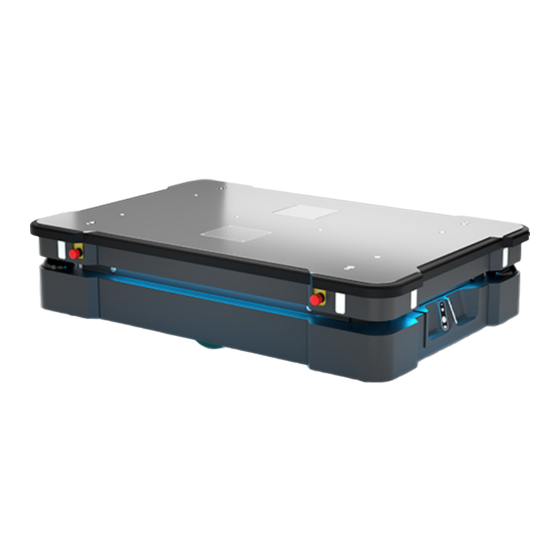
Page 54: Product Presentation
6. Product presentation 6. Product presentation MiR500 is an autonomous mobile robot that can transport loads and pallets up to 500 kg indoors within production facilities, warehouses, and other industrial locations. Users operate MiR500 via a web-based user interface, which is accessed via a browser on a PC, smartphone or tablet. - Page 55 A pallet lift for EU pallets may be mounted on MiR500 enabling it to automate the internal transport of EU pallets. • MiR Lift Pallet Rack Use a MiR Lift Pallet Rack with MiR500 Pallet Lift. The lift places and picks up US standard 40x48 pallets from the rack autonomously. • MiR EU Pallet Rack Use a MiR EU Pallet Rack with MiR500 EU Pallet Lift.
-
Page 56: Identification Label
6. Product presentation To read more about the add-ons, go to www.mobile-industrial-robots.com. 6.2 Identification label The identification label of MiR500 is placed above the MiR controller behind the rear maintenance hatch. Mobile Industrial Robots A/S declares that MiR500 meets the requirements of the applicable EC directives. - Page 57 6. Product presentation • Left position: Autonomous mode. Puts the robot in the Autonomous mode. • Middle position: Stop. Stops the robot. The robot blocks the wheels, you cannot start a mission or drive the robot manually. • Right position: Manual mode. Puts the robot in the Manual mode.
-
Page 58: Mir500 Operating Modes
6. Product presentation • Lets the robot continue operating after powering up or after the operating mode change. Color indication: • Blinking red: The robot is waiting for a user action (clear the emergency stop state, acknowledge the change of operating mode, etc.) On/Off Pressing this button for five seconds turns the robot on or shuts it down. -
Page 59: Mir500 External Parts
6. Product presentation • Reduces the size of the safety zones. • Turns the collision detection off. • Decreases the speed. • Flashes the yellow indicator lights. You can also mute the personnel detection means using the robot interface: • Put the robot into the Manual mode. - Page 60 6. Product presentation 2. Right cover plate: access to safety 9. 3D depth cameras: two pcs., interfaces Aux. safety functions detect objects in front of the robot and Aux. Emergency stop (see Sensor system on page 69) 3. Signal light: eight pcs., two on 10.
- Page 61 6. Product presentation MiR500 top cover View of MiR500 from the top: 1. Not accessible; used for fixation of 3. M10 mooring holes for fixation of the top cover. top module, e.g. MiR500 EU Pallet Lift or MiR500 Pallet Lift. For more information on mounting top modules, see Mounting a top module on page 77.
-
Page 62: Mir500 Internal Parts
6. Product presentation 6.6 MiR500 internal parts Most internal parts of MiR500 are reached through maintenance hatches that open to different compartments: • Front compartment • Rear compartment • Side compartments • Top compartments Front compartment The front compartment holds the electronic components that may need regular service or replacement, such as PC, main control board and safety PLC. - Page 63 6. Product presentation Turn the two levers 180°. The right lever goes from top to bottom and the left lever goes from bottom to top. Then pull out the compartment drawer while holding underneath it and lifting slightly. MiR500 User guide (en) 06/2020 - v.1.4 ©Copyright 2018-2020: Mobile Industrial Robots A/S.
- Page 64 6. Product presentation Front compartment components The front compartment contains the following components: 1. Cable chain 5. Loudspeaker 2. Safe Torque Off contactors 6. Power board: controlling power distribution for motor controller, PC and safety PLC 3. Access point/Router 7. Motor controller carrier board: contains motor controllers and controller for proximity sensors and light indicators.
- Page 65 6. Product presentation Rear compartment The rear compartment holds the robot’s battery. To open the rear compartment: Push the two white buttons. Pull the hatch. MiR500 User guide (en) 06/2020 - v.1.4 ©Copyright 2018-2020: Mobile Industrial Robots A/S.
- Page 66 6. Battery with connector, main in Off position power to the robot 3. Connector for status light band 7. Connection interface for MiR Controller 4. Brake release switch, shown in On position. When turned off, the brakes are released, and the...
- Page 67 6. Product presentation To open a side hatch: turn the two screws 90° counterclockwise with a flat-head screwdriver, and pull the hatch. Side compartment components The left- and right-hand side compartments contain the following components (the same on both sides): 1.
- Page 68 6. Product presentation The two top compartments contain interfaces for top applications and added safety functions. Top compartment components The top compartments contain the following electrical interfaces for top applications. For detailed information, see Interface specifications on page 92. 1. Ethernet 4.
-
Page 69: Sensor System
The safety laser scanners serve three purposes: • They are used for mapping, see also Planning on page 34 and MiR Robot Interface Reference Guide. • They are used to localize the robot in the environment and plan routes between points. - Page 70 6. Product presentation The safety laser scanners detect objects in a plane approximately 200 mm above ground. Objects above or below are not detected by the safety laser scanners. The two safety laser scanners together provide a full 360° view around the robot. When in motion, the safety laser scanners continuously scan the surroundings using a distance of up to 40 m while taking into account and weighting the viewed objects in a so- called "particle filter".
- Page 71 6. Product presentation Signals from safety laser scanners are combined with input from 3D cameras and proximity sensors and used to evaluate if an object or person is in the path of travel. In that case, the robot gradually slows down while trying to avoid the obstacle. If unable to make its way around the obstacle, the robot stops and waits for clearance.
- Page 72 6. Product presentation Safety fields Speed range Field size Protective field all speeds 35 cm When the robot moves backwards, the protective fields switch, so that the largest protective fields are in the driving direction. CAUTION The speed/zone rate is configured to comply with the safety standards of MiR500.
- Page 73 6. Product presentation The following illustrations show the fields of view of the cameras. The two 3D cameras can see objects up to 1700 mm above floor height. MiR500 User guide (en) 06/2020 - v.1.4 ©Copyright 2018-2020: Mobile Industrial Robots A/S.
- Page 74 6. Product presentation The two 3D cameras have a horizontal field of view of 114°. MiR500 User guide (en) 06/2020 - v.1.4 ©Copyright 2018-2020: Mobile Industrial Robots A/S.
-
Page 75: Light Indicators
6. Product presentation Proximity sensors Proximity sensors placed in all four corners of the robot detect objects close to the floor that cannot be detected by the safety laser scanners. Using infrared light, the proximity sensors point downwards and make sure that the robot does not run into low objects such as pallets and forklift forks. - Page 76 6. Product presentation • Signal lights The signal lights at the front and back of the robot show people in the environment if the robot is about to turn a corner or go backwards. The following illustration shows the light indicators. 1.
-
Page 77: Applications
7. Applications 7. Applications You can install top modules on top of MiR500 for specific applications. For more information about top modules, go to our website: http://www.mobile-industrial-robots.com For instructions on how to mount top modules and accessories, contact your distributor. 7.1 Mounting a top module MiR500 has four M10 holes for mounting top modules as shown in Figure 7.1. - Page 78 7. Applications MiR500 external parts on page 59 for more information on the mounting holes. Figure 7.1. Mounting holes on the top of MiR500. M12 lifting holes can also be used to mount top modules. If a top module is mounted using these holes, it is necessary to drill M12 lifting holes in the top application in order to lift the robot.
- Page 79 7. Applications CAUTION Certain top modules may lead to new hazards and/or increased risks that cannot be eliminated or reduced by the risk reduction measures applied by Mobile Industrial Robots. Perform risk assessment according to standard ISO 12100, see Risk assessment on page 12 CAUTION Stay within the specifications for weight and the total payload’s center of gravity, see...
-
Page 80: Lift Modifications
7. Applications 7.2 Lift modifications Additional holes can be added to the MiR500MiR500 Pallet Lift for custom applications. However, it is important not to damage any vital parts of the lift when doing so. Top plate of the lift 1. Material: Steel (S355) 2. - Page 81 7. Applications Bottom frame of the lift 1. Material: Steel (S355) 2. Areas marked with red indicate where you are not allowed to Thickness: 3 mm make modifications, such as drilling holes or mounting Treatment: Powder coating RAL accessories. 7011 NOTICE The drawings above only show where you can make minor modifications without damaging the product.
- Page 82 7. Applications NOTICE It is only possible to modify the MiR500 Pallet Lift, not the MiR500 EU Pallet Lift. MiR500 User guide (en) 06/2020 - v.1.4 ©Copyright 2018-2020: Mobile Industrial Robots A/S.
-
Page 83: Maintenance
8. Maintenance 8. Maintenance The following maintenance schedules give an overview of regular cleaning and parts replacement procedures. The stated intervals are indicative and depend on the operating environment and frequency of usage of the robot. NOTICE Only use approved spare parts. Mobile Industrial Robots disclaims any and all liability if unapproved spare parts are used. -
Page 84: Regular Checks And Replacements
8. Maintenance Parts Maintenance tasks Laser scanners Clean the optics covers of the scanners for optimum performance. Avoid aggressive or abrasive cleaning agents. NOTICE Static charges cause dust particles to be attracted to the optics cover. You can diminish this effect by using the anti-static plastic cleaner (SICK part no. - Page 85 8. Maintenance Part Maintenance Interval Caster wheels Check bearings and tighten. Check weekly and replace as (the four corner needed. wheels) Drive wheels (the Check wheel surfaces for wear. Check every six months and two middle- replace as needed. wheels) NOTICE The robot must be calibrated after...
- Page 86 Check every six months and the floor with e.g. tape around replace as needed. MiR EU Pallet Rack or MiR Lift Pallet Rack are intact and visible. Safety stickers Check if the safety stickers on the Check every six months and robot are still intact and visible.
-
Page 87: Packing For Transportation
8. Maintenance 8.3 Packing for transportation This section describes how to pack the robot for transportation. Original packaging Use the original packaging materials when transporting the robot. The packaging materials are: • The bottom of the box (the pallet) • The lid of the box (the ramp) •... - Page 88 8. Maintenance Packing the robot for transportation To pack the robot for transportation: Shut down the robot. See Shutting down the robot on page 33. Open the rear maintenance hatch. Turn the battery disconnect switch to position OFF. Repeat the steps in section Getting started on page 18 in the reverse order.
- Page 89 8. Maintenance Contact your distributor for more information. CAUTION Lithium batteries are subject to special transportation regulations according to United Nations Regulation of Dangerous Goods, UN 3171. Special transport documentation is required to comply with these regulations. This may influence both transport time and costs. MiR500 User guide (en) 06/2020 - v.1.4 ©Copyright 2018-2020: Mobile Industrial Robots A/S.
-
Page 90: Payload Specifications
• A safe and secure fastening method must be determined during commissioning. The specifications apply to total payloads of up to 500 kg. Side view 500 kg MiR500 User guide (en) 06/2020 - v.1.4 ©Copyright 2018-2020: Mobile Industrial Robots A/S. - Page 91 9. Payload specifications Front view 500 kg MiR500 User guide (en) 06/2020 - v.1.4 ©Copyright 2018-2020: Mobile Industrial Robots A/S.
-
Page 92: Interface Specifications
10. Interface specifications 10. Interface specifications This section describes the specifications of the top application interface. NOTICE Read Safety on page 8 before using the electrical interface. MiR500 has five electrical interfaces divided into two groups: • General purpose interfaces below: •... - Page 93 10. Interface specifications Power An auxiliary power connection for top applications is provided in the top left-hand side compartment. See Connector list on page 103 for more information. Figure 10.1. Pin numbers: female connector viewed from the front (left) and wiring diagram (right). The following table contains the description of the pins of the Power interface.
- Page 94 10. Interface specifications Signal Max. Description number name current 48V safe Turns off in case of a protective or emergency stop. power This output is controlled by the internal safety PLC and the STO contactor to ensure that power is always disconnected from this pin in case of a protective or emergency stop.
- Page 95 10. Interface specifications GPIO A GPIO connection is in the top left-hand side compartment. Figure 10.2. Pin numbers: male connector viewed from the front (left) and wiring diagram (right). A variety of top applications requires a general purpose and "simple-to-use" digital I/O (GPIO).
- Page 96 10. Interface specifications The GPIO supports low current/power devices like relays, contactors, lamps and/or separate PLC units. Figure 10.3. It is intended that outputs and RTNs are used to send signals to the top application, and inputs and 24V pins are used to receive signals from the top application. The GPIO has the following features: •...
- Page 97 10. Interface specifications This enables the GPIO interface to work as input and output to top applications that can be used in missions. The pallet lift feature uses a different kind of communication that is specific to the pallet lift top module. Outputs (O0, O1, O2, O3) can be toggled on and off by the robot in a Set I/O module mission action or manually in Setup > I/O modules.
- Page 98 10. Interface specifications Output pins must be connected to RTN pins, and input pins must be connected to 24V pins. The following table contains the description of the pins of the GPIO interface. Pin number Signal name Max. current Description 1A @ 24V Output 0.
- Page 99 Various protocols are supported, such as Modbus. For more information on how to use Modbus, refer to the how-to guide How to use Modbus with MiR robots found on the Distributor site. The following table contains the description of the pins of the Ethernet interface.
-
Page 100: Safety Interfaces
10. Interface specifications 10.2 Safety interfaces This section describes the safety interfaces located in the right-hand side compartment on the top side of MiR500. Auxiliary emergency stop An Auxiliary emergency stop connection is provided in the top right-hand side compartment. Figure 10.6. - Page 101 10. Interface specifications Signal name Description number E-stop 1 Output signal 1 to safety PLC for emergency stop cir- cuit. Should connect to pin 1. E-stop 2 Output signal 2 to safety PLC for emergency stop cir- cuit. Should connect to pin 2. Reset When high, the robot restarts.
- Page 102 10. Interface specifications The following table contains the description of the pins of the Auxiliary safety functions interface. Pin num- Signal name Description Test output 24V out. Test output 24V out. Safeguarded stop Safeguard dual channel input. Set any or both pin(s) low to enter Emergency stop.
-
Page 103: Connector List
10. Interface specifications Pin num- Signal name Description Unassigned Unassigned. Safe RTN Safe return - Ground. Unassigned Unassigned. Unassigned Unassigned. 10.3 Connector list We recommend the following connectors for the five different interfaces. Dimension draw- Connector name Connector type Phoenix Contact Power M23 6p CA-06P1N8A8008S... - Page 104 10. Interface specifications Figure 10.9. Connector dimensions for GPIO, Auxiliary Emergency Stop, and Auxiliary Safety Functions connectors. MiR500 User guide (en) 06/2020 - v.1.4 ©Copyright 2018-2020: Mobile Industrial Robots A/S.
Need help?
Do you have a question about the 500 and is the answer not in the manual?
Questions and answers