
Related Manuals for Det-Tronics R8471A


Summary of Contents for Det-Tronics R8471A
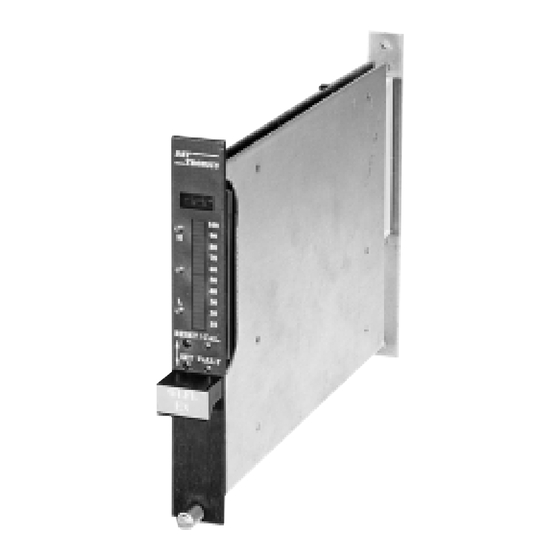
- Page 1 Instructions 95-8398-02 Combustible Gas Controller R8471A Detector Electronics Corporation 6901 West 110th Street • Minneapolis, Minnesota 55438 USA 2/95 Tel: 612.941.5665 or 800.765.3473 • Fax: 612.829.8750...
-
Page 2: Table Of Contents
Table of Contents Section I - General Information Section IV - System Maintenance DESCRIPTION ............1 ROUTINE MAINTENANCE ........23 Manual Check of Output Devices......23 FEATURES..............1 Checkout in Normal Mode.........23 SPECIFICATIONS.............1 Sensor Replacement.........23 Controller Calibration ........24 SYSTEM OPERATION..........3 Transmitter Calibration .......24 Sensor ..............3 Transmitter ............3 TROUBLESHOOTING..........24 Controller.............3... -
Page 3: Section I - General Information
R8471A Section I General Information DESCRIPTION The R8471A Combustible Gas Controller monitors a 4 to 20 milliampere (ma) dc signal generated by a Det- Tronics combustible gas sensor/transmitter assembly. The single channel system operates in the range of 0 to 100% LFL (lower flammable limit). Controller... -
Page 4: Controller Dimensions In Inches (Centimeters)
K Series transmitter are fully ±3 percent full scale up to 2.5 percent methane gas compatible with the R8471A Controller, they have not been FMRC tested and approved for use with the by volume in air (50% LFL), ±5 percent full scale up to 5 percent methane gas by volume in air (100% R8471A Controller. -
Page 5: System Operation
If an over-range condi- tion occurs, the display flashes and the highest Det-Tronics combustible gas sensors use a catalytic reading latches on. Since this display is always type sensing element and operate in the range of 0 to on, it also functions as a power indicator. -
Page 6: Setpoints
6. Cal LED—Illuminated while the controller is in the mally energized and becomes de-energized upon calibrate mode. detection of a system fault. NOTE Premium Model—The premium model is furnished with a set of four relays in place of the four solid state In the Setpoint Display or Setpoint Adjust mode, a flashing alarm LED identifies the particular set- outputs. -
Page 7: Operating Modes
NOTE An alarm condition will normally over-ride a fault con- The fault code will be shown for about 2 seconds dition unless the fault condition occurred first (except out of every 5 seconds. The gas concentration F10, F2X). However, faults that affect the actual func- at the sensor will be displayed during the remain- tion of the controller (F50, F60, F70, F9X) can impair the ability of the controller to maintain an alarm out-... -
Page 8: R8471 Controller Flow Chart
POWER-UP HOLD RESET 7 SECONDS TIME DELAY 9.0 SECONDS HOLD HOLD HOLD RESET RESET RESET RESET BASIC FORCED SETPOINT CALIBRATE NORMAL RESET RESET DISPLAY < 0.5 SECOND 0.5 SECOND 1.0 SECOND RESET SENSOR REPLACE 1.0 SECOND RESET SETPOINT PUSHED WITH ADJUST SET? MUST BE PRESSED BEFORE THE ZERO... -
Page 9: Section Ii - System Installation
centration. Each value is displayed for approximately SETPOINT ADJUST 2 seconds. After completing the sequence, the con- troller automatically returns to the Normal operating The Setpoint Adjust mode is entered by depressing mode if the Reset button is no longer being the Set button for approximately one second. -
Page 10: General Wiring Requirements
For additional information on determining quantity and GENERAL WIRING REQUlREMENTS placement for sensors in a specific application, refer to Instrument Society of America (ISA) Transaction NOTE Volume 20, Number 2, titled “The Use of Combustible The wiring procedures in this manual are intend- Detectors in Protecting Facilities from Flammable ed to ensure proper functioning of the device Hazards”. -
Page 11: Sensor Separation
It is recommended that conduit breathers also be Table 3—Maximum Wiring Distances – Controller to K Series Transmitter used. In some applications, alternate changes in temperature and barometric pressure can cause Wire Size Maximum Controller to “breathing”, which allows the entry and circulation of Transmitter Distance Diameter moist air throughout the conduit. -
Page 12: Sensor Installation
The shorting plug, which attaches to the connector being used. Note that maximum wiring distances board, must be in place at all times that the sensor is also vary with the specific transmitter model being operating. used. Table 4 shows the maximum separation dis- tance allowed for a given wire size when using K The calibration cup can remain on the sensor after Series Transmitters. -
Page 13: Sensor/Transmitter Wiring
USER SUPPLIED TUBING (1/4 INCH I.D.) ADJUST SENSOR VOLTAGE TO MEASURE 3.3 VDC BETWEEN THE + AND – TERMINALS WITH SENSOR AND SHORTING PLUG INSTALLED SHORTING PLUG CONNECTOR BOARD JUNCTION BOX SENSOR CALIBRATION CUP APPLY CALIBRATION GAS HERE JUNCTION BOX SENSOR SEPARATION CONNECTOR BOARD TRANSMITTER... -
Page 14: Controller Wiring
handling, taking care not to touch the terminals JUNCTION BOX or electronic components. For more information CONNECTOR BOARD on proper handling, refer to Service Memo form TRANSMITTER MODULE PLUGS IN HERE 75-1005. CONDUIT SEAL REQUIRED HERE CONDUIT 3. Remove the transmitter module from the junction box. -
Page 15: Dimensions Of The Mounting Rack
CONTROLLER POSITIONS FOR: DIM. (A) DIM. (B) DIM. (C) DIM. (D) DIM. (E) FIRE INCH INCH INCH INCH INCH 19.00 482.6 18.30 464.8 17.36 440.9 4.00 101.6 6.97 177.1 15.06 382.6 14.36 364.7 13.42 340.9 11.13 282.6 10.43 264.9 9.49 241.1 9.16 232.7 8.46... -
Page 16: Figure
R8471 CONTROLLER 4-20 MA – – – CURRENT OUTPUT ISOLATED OUTPUT CURRENT LOOP CHASSIS GROUND CHASSIS GROUND 18 TO 32 POWER 18 TO 32VDC POWER – – – GROUND POWER SENSOR TRANSMITTER POWER SENSOR SIGNAL – SIGNAL – – EXTERNAL RESET EXTERNAL RESET SENSOR RESET... -
Page 17: Controller Programming
PREMIUM CONTROLLER – The relay outputs (termi- +24 VDC (+60 VDC MAXIMUM) nals 9 to 16) are programmed for the desired opera- tion using the procedure described in the “Controller 1N4004 TYPICAL Programming” section. R7484 OPEN COLLECTOR OUTPUT BASE CONTROLLER – Connections to open collec- tor transistor outputs are made at terminals 10, 12, 14, 100K and 16. -
Page 18: Latching/Non-Latching Relays
place it on the NC and center pins. The pin groups 3. If a sensor separation kit is used, interconnecting are identified as follows: wiring is correct and shorting plug is installed. J2 – High Alarm 4. All cable shields are properly grounded. J3 –... -
Page 19: Setpoint Adjustment
NOTE To check the present levels, use the “Setpoint Display When power is applied to the controller, it enters Mode” described below. To change the values, use a time delay mode to allow the sensor output to the “Setpoint Adjustment Procedure”. stabilize before beginning normal operation. -
Page 20: Calibration
2. Press and hold the Set button for one second. — If the transmitter is replaced The digital display indicates the present low alarm — If the controller is replaced setpoint and the Low LED blinks. Press the Reset — If the sensor is exposed to a high level of com- button to increase the reading or the Set button to bustible gas. -
Page 21: Calibration Procedure
using a gas/air mixture of the gas that is intended to cover, therefore, the hazardous area must be de- be detected. If several different combustible gases classified. can be present, calibrate to the least detectable gas. When transmitter calibration is performed, an ini- If a calibration mixture of the gas to be detected is not tial calibration of the controller must be completed available, the system can be calibrated using a stan-... -
Page 22: Setting Controller Default Values
accuracy). The controller calibration procedure If there is any indication of the presence of com- can then be used for all subsequent calibrations. bustible gas at the sensor, calibration or mainte- nance should not be performed. Setting Controller Default Values (Required for Transmitter Calibration) The location must be de-classified prior to cali- bration. -
Page 23: Figure 14 Calibration Sequence For K Series
SENSITIVITY CHECK ZERO SPAN ZERO SPAN % LFL % LFL 2. APPLY CALIBRATION GAS. 1. SET ZERO. CHECK SENSOR SENSITIVITY. ZERO SPAN ZERO SPAN % LFL 4. REMOVE CALIBRATION GAS. WHEN % LFL 3. SET SPAN. B1123 READING IS BELOW ALARM LEVEL, CALIBRATION METER MAY BE REMOVED. -
Page 24: Controller Calibration Procedure
is lost. The calibration procedure cannot be sor during the zero portion of the calibration pro- aborted at this point. Sensor calibration must be cedure is not recommended. performed. 3. Depress and hold the Reset button until the CAL 4. Remove the sensor junction box cover. LED is illuminated and the digital display starts to flash (approximately 9 seconds). -
Page 25: Section Iv - System Maintenance
loads and connecting a dc ammeter between the open sensor wiring, and various other problems that two 4 to 20 ma terminals, by connecting a dc could prevent proper response to a dangerous level ammeter in series with the load, or by connecting of gas. -
Page 26: Controller Calibration
Boron trifluoride Phosphate esters A. Materials that can clog the pores of the sintered metal flame arrestor and reduce the gas diffusion Significantly longer sensor life can be obtained by rate to the sensor are: using the Det-Tronics poison resistant sensor. -
Page 27: Troubleshooting Guide
Table 5—Troubleshooting Guide Problem Possible Cause No faceplate indicators 1. Wiring to external power source. illuminated. 2. Input power failure. FAULT LED on, digital 1. Power-up time delay (up to 5 minutes). display blank. 2. If condition continues after 5 minutes, repeat power-up. If problem continues, replace controller. -
Page 28: Replacement Parts
Always calibrate after replacing the sensor. Significantly longer sensor life can be obtained by using the Det-Tronics poison resistant sensor. Refer to the “Ordering Information” section for a list of parts. D. Exposure to high concentrations of combustible gases. - Page 29 ITALY Facsimile (713) 782-4287 Telephone (39) 2 33 20 06 35 Facsimile (39) 2 39 00 11 93 Detector Electronics (UK) Limited Riverside Park, Poyle Road Det-Tronics Scandinavia AB Colnbrook Costerweg 5 Slough, Berkshire P O Box 46 SL3 OHB...
-
Page 30: Ordering Information
Silicone Free Grease from the controller. When ordering please specify: Rain Shield Splash Guard R8471A Combustible Gas Controller Dust Cover (Stainless Steel) Specify base or premium model, 3U or 4U height. Dust Cover (Porex) Sample Draw Assembly (one "T" fitting) NOTE Sample Draw Assembly (two "T"... - Page 32 Recommended Test Form Detector Detector Date Date Date Remarks Number Location Installed Checked Calibrated...
- Page 33 Fault Record Sheet Detector Date Time System Status Operator Comments Affected 95-8398...
- Page 34 Printed in USA Detector Electronics Corporation 6901 West 110th Street • Minneapolis, Minnesota 55438 USA Tel: 612.941.5665 or 800.765.3473 • Fax: 612.829.8750...
Need help?
Do you have a question about the R8471A and is the answer not in the manual?
Questions and answers