Table of Contents
Advertisement
Quick Links
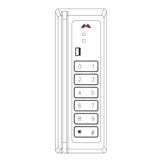
MR10/20 Magnetic Card Reader
Installation and Specifications
1. General:
The MR10/20 family of magnetic stripe card readers are designed for reading standard or high-coercivity
magnetic stripe cards. The MR10/20 provides a TTL interface to an access control panel and the MR20
also provides a 12-key keypad for PIN entry. The following paragraphs describe instructions for installing
and maintaining the card reader.
2. Mounting the Reader:
Find a suitable location to anchor the reader mounting bracket. The reader may be mounted vertically or
horizontally. See recommended orientation. The mounting of the reader does not require a junction box.
However, rigid conduit is required for outdoor application. A single gang junction box may be used to
provide a transition to rigid conduit. If a single gang junction box is used, a wall plate (optional) may be
used to cover the junction box. The reader is then secured to the mounting bracket using a screw. Refer
to figures for reader dimensions and typical junction box usage.
3. Reader Wiring:
The reader has a RJ-11 modular jack for easy field connection. A small piece of pre-terminated cable is
supplied with each standard reader for field wiring. The pre-terminated cable has nonstandard color.
Refer to pin number if the pre-terminated cable is not used. Cable with wires of 24AWG or larger are
recommended for field wiring.
4. Connecting the Keypad:
The MR20 reader provides a 12-key keypad for PIN entry. The flex tail of the keypad is connected to the
electronic board via a ZIF (zero insertion force) connector. The contacts are engaged/disengaged by a
moving slide. Care must be exercised when connecting and disconnecting the keypad. When connecting
the keypad to the board, open the slide as shown. Insert the electronics into the housing and insert flex
tail in the ZIF connector. Then, close the slide to engage the contacts. To disconnect the keypad, follow
the previously described steps in reverse.
CAUTION: DO NOT DISCONNECT KEYPAD WITHOUT DISENGAGING THE CONNECTOR!
COFIDENTIAL: For installation and maintenance use only. DONOT distribute.
Mercury Security © 2013
2355 MIRA MAR AVE. LONG BEACH, CA 90815-1755, (562)986-9105 FAX (562) 986-9205
MR10/20
DOC 10107-0000
This device complies with part 15 of the FCC Rules.
Operation is subject to the following two conditions: (1) This
device may not cause harmful interference, and (2) this
device must accept any interference received, including
interference that may cause undesired operation.
REV 2.01
www.mercury-security.com
Page 1
Advertisement
Table of Contents

Subscribe to Our Youtube Channel
Related Manuals for Mercury Security MR10


Summary of Contents for Mercury Security MR10
- Page 1 The MR10/20 family of magnetic stripe card readers are designed for reading standard or high-coercivity magnetic stripe cards. The MR10/20 provides a TTL interface to an access control panel and the MR20 also provides a 12-key keypad for PIN entry. The following paragraphs describe instructions for installing and maintaining the card reader.
- Page 2 This can be accomplished by tying the mounting bracket to earth ground locally (e.g. grounded conduit). 8. Dip Switch Settings: The DIP switches (S1 & S3) on the MR10/20 readers are used to select a preset format. This preset format determines how the card is interpreted, the functions for the LED and buzzer, and the output signal format, etc.
- Page 3 15** CLOCK/DATA 1-WIRE LED 9. MR10/20 Standard Format Code Summary: The following formats are supported in standard models (300x2-0000/310x2-0000). Unless otherwise indicated, the LED input line controls both LEDs (low=green, high=red); the BUZZER input controls the buzzer (low = activate); a good read is signaled by a flash of the green LED; a bad read is signaled by a flash of the red LED and a double beep of the buzzer.
- Page 4 Timing: clock/data: period 1mS setup/hold time 400uS, clock pulse width 200uS typical data 1/data 0: period, 3mS for Wiegand data, 1mS for mag stripe data pulse width 50uS typical Mercury Security © 2013 MR10/20 DOC 10107-0000 REV 2.01 Page 4...
- Page 5 0-95% RHNC, standard 100% (-OW option) Reader Mounting Dimensions: 1.30 [33] 0.15 [4] .75 [19] Ø .18 [4.5] Ø MOUNTING HOLE 3.30 [84] 2.60 [66] 1.00 [25] DIMENSION: INCH [mm] Mercury Security © 2013 MR10/20 DOC 10107-0000 REV 2.01 Page 5...
- Page 6 This product is not intended for, nor is rated for operation in life-critical control applications. Mercury Security is not liable under any circumstances for loss or damage caused by or partially caused by the misapplication or malfunction of the product. Mercury Security's liability does not extend beyond the purchase price of the product.
Need help?
Do you have a question about the MR10 and is the answer not in the manual?
Questions and answers