Table of Contents
Advertisement
Quick Links
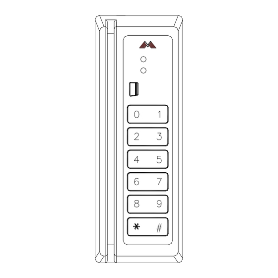
MR5 Magnetic Card Reader
Installation and Specifications
1. General:
The MR5 magnetic stripe card reader is designed for reading standard or high-coercivity magnetic stripe
cards. The reader has a TTL interface with selectable clock/data and data 1/data 0 signaling. A bi-color
LED and a buzzer are standard.
maintaining the card reader.
2. Mounting the Reader:
Find a suitable location to anchor the reader mounting bracket. The reader may be mounted vertically or
horizontally. See recommended orientation. The mounting of the reader does not require a junction box.
However, rigid conduit is required for outdoor application. A single gang junction box may be used to
provide transition to rigid conduit. If a single gang junction box is used, a wall plate (optional) is available
to cover the junction box. The reader is then secured to the mounting bracket using a UNC6-32 3/8
screw. Refer to figures for reader dimensions and typical junction box usage.
3. Weather Proofing the Reader:
MR5 reader is rated for outdoor use over extended
temperature. A tube of dielectric grease is supplied for
the installer to coat field connections to seal out moisture.
After field connection/configuration is made, the grease is
to be applied on the DIP switch slides and the modular
jack to seal out moisture. Squeeze some grease into the
modular jack before connecting the cable.
Do not use sealant to seal reader case to wall.
Doing so will trap water in the reader and may cause
damage to the reader.
4. TTL Interface and Reader Wiring:
The TTL interface has the standard 6-wire interface widely
used in the access control application. The reader has a
RJ-11 modular jack for easy field connection.
piece of pre-terminated cable is supplied with each reader
for field wiring. Refer to pin number if the pre-terminated
cable is not used. Cable with wires of 24 AWG or larger
are recommended for field wiring. If a shielded cable is used, connect the cable shield to either earth
ground or signal ground at one end only.
CONFIDENTIAL: For installation and maintenance use only. DO NOT distribute.
Mercury Security © 2015
2355 MIRA MAR AVE. LONG BEACH, CA 90815-1755, (562)986-9105 FAX (562) 986-9205
The following paragraphs describe instructions for installing and
A short
MR5
DOC 10107-0012
This device complies with part 15 of the FCC Rules.
Operation is subject to the following two conditions: (1) This
device may not cause harmful interference, and (2) this
device must accept any interference received, including
interference that may cause undesired operation.
MODULAR PLUG
REV 2.00
www.mercury-security.com
6 (BLK) GROUND
5 (ORG) BUZZER/LED/CP
4 (BRN) LED
3 (WHT) DATA 1/CLOCK
2 (GRN) DATA 0/DATA
1 (RED) +5 or +12Vdc
depends on model
Page 1
Advertisement
Table of Contents

Subscribe to Our Youtube Channel
Related Manuals for Mercury Security MR5


Summary of Contents for Mercury Security MR5
-
Page 1: Mounting The Reader
1. General: The MR5 magnetic stripe card reader is designed for reading standard or high-coercivity magnetic stripe cards. The reader has a TTL interface with selectable clock/data and data 1/data 0 signaling. A bi-color LED and a buzzer are standard. -
Page 2: Specifications
This can be accomplished by tying the mounting bracket to earth ground locally (e.g. grounded conduit). 6. Reader Configuration: The DIP switches on the MR5 reader are used to configure the reader. See table below: SW-4 SW-3... - Page 3 -40 to +75 degrees C, operating Humidity: 0-100 % RHNC, standard Reader Mounting Dimensions: 1.30 [33] .18 [4.5] Ø MOUNTING HOLE .75 [19] Ø 3.30 [84] 2.60 [66] 1.00 [25] DIMENSION: INCH [mm] Mercury Security © 2015 DOC 10107-0012 REV 2.00 Page 3...
- Page 4 This product is not intended for, nor is rated for operation in life-critical control applications. Mercury Security is not liable under any circumstances for loss or damage caused by or partially caused by the misapplication or malfunction of the product. Mercury Security’s liability does not extend beyond the purchase price of the product.
Need help?
Do you have a question about the MR5 and is the answer not in the manual?
Questions and answers