Table of Contents
Advertisement
Quick Links
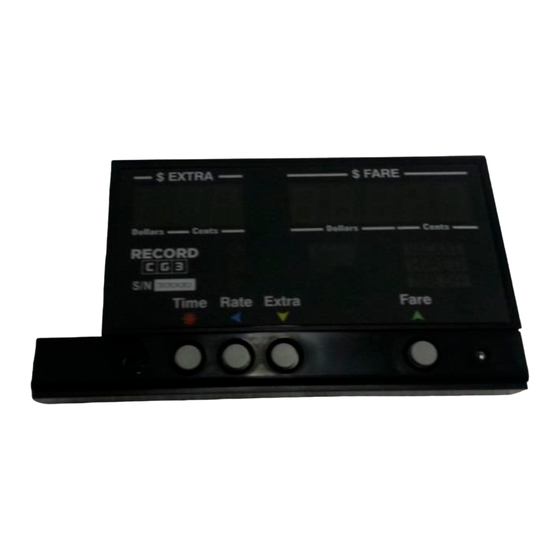
CG3 Setup Instructions
Figure 1
The CG3 consists of the following components:
1.
CG3 taximeter display unit.
2.
Cable-and-bracket assembly, with attached RS-232 Serial communication cable.
3.
Seal-screw and hex-nut.
4.
(Optional) USB mini-B adaptor.
Figure 2: D9 Serial Connector. Used for RS-232 communication. You will need a male 9-pin
Connector if you are using a Black Cat adapter for sensing motion, or a female connector if you are
communicating with most Dispatch Terminals (MDT). IMPORTANT: See section 2.2
2
1
1
4
3
Advertisement
Table of Contents

Related Manuals for Record CG3

Summary of Contents for Record CG3
- Page 1 CG3 Setup Instructions Figure 1 The CG3 consists of the following components: CG3 taximeter display unit. Cable-and-bracket assembly, with attached RS-232 Serial communication cable. Seal-screw and hex-nut. (Optional) USB mini-B adaptor. Figure 2: D9 Serial Connector. Used for RS-232 communication. You will need a male 9-pin Connector if you are using a Black Cat adapter for sensing motion, or a female connector if you are communicating with most Dispatch Terminals (MDT).
- Page 2 IMPORTANT: While the CG3 Taximeter does contain internal protection against most catastrophic high-current instances, some precautions still need to be taken by the operator to protect the CG3 Taximeter roof light circuit against unforeseen extreme current surges that can occur in the often hostile automotive environment (with regards to sensitive electronics).
-
Page 3: How To Enter Programming Mode
To activate the Config Switch, you have to short the two plated holes together. This can be done, either with a programming pin (these are usually provided with CG3 upon purchase), or simply with a piece of wire (we find that a paper-clip works the best). - Page 4 If a security code has been set, the user will be prevented from proceeding through the following steps. By default, the security code is 0: Figure 5: The Security Code Prompt, which locks against proceeding to programming mode when an optional security code has been previously set. If no passcode has been set, simply press to proceed to Section 4.0: Programming Menu.
-
Page 5: Programming Menu
Set Rates (as described in Section 5.0) - Set Calibration (mileage). - OBD2 Settings - Load Rates from USB flash drive. Configure CG3 for dispatch communication Clean taximeter. Clears all rates and calibration. Set Security Code (Optional)* * For locking Programming Mode against unauthorized tampering. -
Page 6: Programming Rates
Programming Rates Button functions are shown to the left. A flashing cursor on the $Fare display indicates which digit can be adjusted. Use the buttons to set and navigate the rate values sequentially. The left-hand ($EXTRA) display indicates the current value being adjusted ... - Page 7 5.1 Individual Rates Section: The Rate Number that you are currently setting will be indicated by the far-left digit (see below). The current Rate number (in this case, Rate - Flag (Initial) Charge - Charge-per-hour (Wait-Time charge) - First drop distance (5.2) - Subsequent or Second drop distance (5.2) - Fare increments 5.2 Subsequent Rates –...
-
Page 8: Calculating Drop Distances
Calibrating Mileage This section is required if you are using Vehicle Speed Sensor (VSS) pulses to provide distance to the CG3 (as opposed to an OBDII interpreter device).Enter Configuration Mode (see section 4.4.1), and press... - Page 9 Set the Filter Value Upon entering Calibration Mode, you will first have the option to set the filter value, F1 (figure 15). The filter value is a feature that allows for re-sampling of individual mileage pulses to ensure that they are not noise “spikes” that could be interpreted as valid VSS pulses.
- Page 10 Set the Signal-Conditioner Value (VSS Sensitivity) CG3 models with serial number 31,000 and up have a built-in signal conditioner that allow for adjusting the sensitivity of the VSS detector circuit. This is helpful in either eliminating noise which can lead to improper readings (i.e.
-
Page 11: View / Manually Set Calibration Value
View / Manually Set Calibration Value Next, the current calibration setting will be displayed (figure 16). You have the option to: a) manually change the current calibration setting, or b) skip changing the calibration value (in order to proceed to the calibration procedure). Figure 7: Current calibration setting a) To adjust the current calibration setting: ... -
Page 12: Calibration Procedure
Procedure figure 18: Signal Conditioner setting value displayed If your CG3 has the built-in Signal-Conditioner i.e., the Serial Number is 31000 or greater (section 4.7), you can fine-tune adjust the sensitivity of the VSS detector circuit repeatedly while in calibration mode. This is described next: While in Calibration Test Mode: ...
Need help?
Do you have a question about the CG3 and is the answer not in the manual?
Questions and answers