Table of Contents
Advertisement
Quick Links
8476 ELKAY MICROWAVE TIMER INSTRUCTIONSv6_Layout 1 02/11/2009 09:22 Page 1
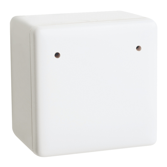
microwavetimer
microwavetimer fitting and operating instructions
microwavetimer - three wire
Product: 380A-1 Three wire
Rating at 240V ac
• Incandescent 16A • Compact Fluorescent 16A
• Resistive
16A • Fluorescent 16A • Time Delay 2min - 2h
1.
Ensure the mains power is switched off before any wiring takes place.
2.
Fit the back box to the wall for mounting using appropriate screws and
fixings (not supplied).
3.
Set the dip switches to the required time settings (See diagram 2).
4.
Connect the Live In, Live Out (Switch Live) and the Neutral into the marked
terminals (See diagram 1).
5.
To adjust lux level, locate lux level adjuster on the circuit board where the
word LUX is printed. Turn anticlockwise for plus + and clockwise for minus -.
6.
To adjust sensitivity, locate SEN on the opposite side of the circuit board
turn clockwise for plus + and anticlockwise for minus -.
7.
Please ensure white faceplate is attached before initialisation with holes at the top.*
8.
Apply the mains power. Your load will turn on and a red light will begin flashing for 2 minutes and then will flash rapidly for 1 minute.
At the end of this 3 minute cycle the load will turn off. The load will switch on again once further movements are detected.
9.
Please note the red LED should be clearly seen through the hole in the faceplate. The unit is supplied with the default setting of max
lux and sensitivity levels.
N.B. For flush mounting please ensure that it fits into a 35mm backbox.
Wiring diagram for a three wire Microwave unit
(For additional products to be added see Diagram 3).
TOP
N SL L
* If faceplate is clipped on the wrong way Lux level adjustment
will not work correctly (See TOP markings).
All wiring should be carried out by a competent person or a qualified electrician and should be fitted to IEE 17th Edition Wiring regulations BS7671:2008.
Diagram 1
LIVE IN
LIVE IN
NEUTRAL
NEUTRAL
LIVE OUT
LUX
SEN
N
N
SL
L
L
Call +44 (0) 1675 468222 or click www.elkay.co.uk
energysense
Diagram 2
Please note that the black bar denotes the position
of the dip switch.
4.
4.
3.
3.
2.
2.
1.
1.
2 mins
5 mins
10 mins
4.
4.
3.
3.
2.
2.
1.
1.
20 mins
25 mins
30 mins
4.
4.
3.
3.
2.
2.
1.
1.
50 mins
60 mins
70 mins
4.
4.
3.
3.
2.
2.
1.
1.
90 mins
100 mins
110 mins
4.
3.
2.
1.
15 mins
4.
4.
3.
3.
2.
2.
1.
1.
40 mins
4.
3.
2.
1.
80 mins
4.
4.
3.
3.
2.
2.
1.
1.
120 mins
Advertisement
Table of Contents

Related Manuals for Elkay energysense 380A-1


Summary of Contents for Elkay energysense 380A-1
- Page 1 8476 ELKAY MICROWAVE TIMER INSTRUCTIONSv6_Layout 1 02/11/2009 09:22 Page 1 microwavetimer energysense microwavetimer fitting and operating instructions microwavetimer - three wire Product: 380A-1 Three wire Rating at 240V ac • Incandescent 16A • Compact Fluorescent 16A • Resistive 16A • Fluorescent 16A • Time Delay 2min - 2h Ensure the mains power is switched off before any wiring takes place.
- Page 2 8476 ELKAY MICROWAVE TIMER INSTRUCTIONSv6_Layout 1 02/11/2009 09:22 Page 2 microwavetimer energysense microwavetimer fitting and operating instructions Diagram 3 Plan view of Microwave pattern. AREA OF HIGH SENSITIVITY AREA OF LOW SENSITIVITY Diagram 4 Wiring diagram for additional Microwave units.
Need help?
Do you have a question about the energysense 380A-1 and is the answer not in the manual?
Questions and answers