Table of Contents
Advertisement
Advertisement
Table of Contents

Related Manuals for Aslan Machine SA04-u450ma Series

Summary of Contents for Aslan Machine SA04-u450ma Series
- Page 1 USER'S MANUAL AUTOMATIC UPCUT MITER SAW SA04-u450 series a.k.a PKS-503...
- Page 2 ● ● ...
-
Page 3: Table Of Contents
CONTENTS 1. General Information 1.1. Introduction 1.2. Distributor 2. Machine’s Description and Purpose of Use 2.1. Machine’s description 2.2. Technical features 2.3. Cutting diagram 2.4. Overall dimensions 2.5. Part lists and technical drawings for cutting mechanism 2.6. Electric and pneumatic control panel 3. -
Page 4: General Information
The technical drawings and details contained in this manual are a guide for the operator. 1.2. DISTRIBUTOR Aslan Machine, Inc. 20423 Waters Point Lane, Germantown, MD 20874 Phone: +1-301-528-1696 Fax: +1-301-542-0185 Website: www.aslanmachine.com E-mail: info@aslanmachine.com... -
Page 5: Machine's Description And Purpose Of Use
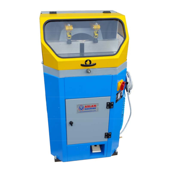
2. MACHINE’S DESCRIPTION AND PURPOSE OF USE 2.1. MACHINE’S DESCRIPTION This is an automatic up-cut saw with a circular saw blade for cutting PVC, aluminum and wood profiles at straight and miter angles. The operator can adjust the cutting speed of the saw blade via a knob on the air piston for the material type and the size. - Page 6 Figure – 1a General front view of the machine (SA04-u450ma-1 model) and its components. Note: for safety reasons the motor does not start moving up until the top safety cover is closed and the clamps are activated.
- Page 7 SA04-u450ma-1 SA04-u450ma-2 Works with foot pedal for cutting. Works with two-hand push buttons for cutting. Figure – 1b General look of the two sub-models of SA04-u450ma series. Check which model you have.
-
Page 8: Technical Features
2.2. TECHNICAL FEATURES Technical Features (Metric) 1.5kW SA04- D=450 mm 62x73x112 220V 60Hz 3000 rpm 130 kg u450 d=32 mm l/min ma-1 3-Phase 1.5kW SA04- D=450 mm 62x82x112 220V 60Hz 3000 rpm 130 kg u450 d=32 mm l/min ma-2 3-Phase Technical Features (American) -
Page 9: Cutting Diagram
2.3. CUTTING DIAGRAM Figure - 2 Cutting Diagram with 450 mm saw blade. -
Page 10: Overall Dimensions
2.4. OVERALL DIMENSIONS MODEL: SA04-u450ma-1 MODEL: SA04-u450ma-2 Figure – 3 Overall Dimensions, in terms of millimeters (1 inch = 25.4 mm) - Page 11 2.5. TECHNICAL DRAWINGS AND PARTS LIST Figure -4a Parts list for the motor and work table components SA04-u450ma-1...
- Page 12 Figure -4b Parts list for the additional components for SA04-u450ma-2...
- Page 13 Conveyor (optional item) Conveyor (optional item) Figure – 6 A Typical conveyor attachments (Conveyor is an optional feature and the conveyor supplied to you might be also different than this, please check with us about how to connect your conveyor to the machine.)
-
Page 14: Electric And Pneumatic Control Panel
2.6. ELECTRIC AND PNEUMATIC CONTROL PANEL The electric and pneumatic control panel enables you to make adjustments regarding the air pressure. The cover of the panel has to be kept closed/locked during cutting. Before servicing the machine: TURN OFF THE ELECTRIC AND PNEUMATIC SUPPLY CONNECTIONS. - Page 15 WARNING: DO NOT operate the machine if the air pressure is less than 60 psi because the clamps will not safely hold the part you are cutting. DO NOT operate the machine with the top safety cover open. DO NOT disconnect the safety cover switch.
-
Page 16: Safety
3. SAFETY 3.1. SAFETY INFORMATION The symbols shown hereunder must be read with a special attention. Not reading or observing them may cause damage to the equipment or personal injury. IMPORTANT The IMPORTANT symbol above shows that it is necessary to pay special attention at the specified operation. -
Page 17: Accident Prevention
3.2. ACCIDENT PREVENTION 3.2.1. Our machines are manufactured in accordance with EN 60204-1 and EN 292-2 CE safety directives, which international safety directives. 3.2.2. It is the responsibility of the employer to warn his staff against accident risks, to train them on prevention of accidents, to provide the necessary safety equipment and devices for the operator’s safety. -
Page 18: General Safety Information
3.3. GENERAL SAFETY INFORMATION 3.3.1. The power cable should be placed in a way that nobody can step on it or nothing can be placed on it. Special care must be taken regarding the inlet and outlet sockets. 3.3.2. If the power cable is damaged during operation, don't touch it. Unplug it from the power source. - Page 19 3.3.11. Use safe working position, always keep your balance. 3.3.12. Keep your machine always clean for safe operation. Follow the instructions at maintenance and replacement of accessories. Check the plug and cable regularly. If damaged, have it replaced by a qualified electrician. Keep handles free from any oil and grease.
-
Page 20: Safely Transporting The Machine
4. SAFELY TRANSPORTING THE MACHINE IMPORTANT The transporting must be done by qualified personnel only. The machine should be transported by lifting with proper equipment (The machine should not be touching the ground during the transport). Don’t lift the machine before making sure that lifting devices or other equipment is placed properly under the machine. - Page 21 Figure – 7 Typical safe distances around the machine (when installed without the optional conveyor) Please add also the conveyor distance if you ordered it.
- Page 22 Make sure the machine is leveled. If your machine came with conveyors, attach them to the Use the level adjustment bolts on the feet machine by using the bolts that came with it. Then make the adjustments to level it. Figure –...
-
Page 23: Electric Connection
5.2. ELECTRIC CONNECTION 5.2.1. The three-phase power cable socket must be installed by your electrician. 5.2.2. Check the power supply before powering the machine. 5.2.3. Make the electric socket connections when the MAIN POWER SWITCH on the machine is set to 0. (i.e. cut the power going to the machine.) CAUTION ! *The power connection must be made by a qualified electrician. - Page 24 Figure – 9 Saw blade direction must be correct for safe operation. To correct the rotation direction of the saw blade, connect the machine to an electric power plug for 3-phase, and follow these instructions: 1. Press the Motor Start Button to operate the saw blade. 2.
- Page 25 Figure – 10a Pneumatic system of the machine inside cabin. Adjusting the lowering speed Adjusting the rising speed Figure – 10b Speed adjustments. (Before putting your hands inside the saw blade cabin, turn off the power to the machine for safety).
-
Page 26: Machine Safety Information
6. MACHINE SAFETY INFORMATION 6.8.1. It is not allowed to operate the machine with its safety cover and other safety components removed. 6.8.2. Your machine operates with 220 V or 400V (440V) ~ 3 Phase 50Hz (60Hz). Use a qualified electrician only for the installation. 6.8.3. -
Page 27: Operation
7. OPERATION The automatic up-cut saw cuts non-ferrous aluminum, PVC profiles and PVC materials. The operator can adjust (manually via knob) the cutting speed according to the material type by turning the air flow constrictors inside the machine cabin. Inner and outer sharp edges of a carbide tipped circular saw blade ensures high quality clean cutting results. - Page 28 Description of the items on the cutting zone.
- Page 29 Spray mist lubrication items and their locations on the machine. Spray mist lubrication system is optional and comes only if you order it along with the machine. It is essential to have it for cutting aluminum.
- Page 30 Figure 11 The clamping cylinders must be at a correct position to prevent damage to the cylinders themselves.
-
Page 31: Adjusting The Air Pressure
7.1.8. if you purchased our optional conveyor, adjust the cutting length of the material by using the measuring system with length stop units on the conveyor. After adjusting the cutting length, fix the profile support fence by tightening the stopper on the conveyor. 7.1.9. - Page 32 7.1.3. The manufacturer recommends the following oils for the air conditioning unit: TELLUS C 10 BP ENERGOL HLP 10 MOBIL DTE LIGHT Any brand of airtool oil. Any brand Number 10 machine oil. Air connection location.
- Page 33 Figure – 12 Air conditioning Unit.
-
Page 34: Checking Angle Adjustment Of Saw Blade And Bridge
7.3. CHECKING ANGLE ADJUSTMENT OF SAW BLADE AND BRIDGE If you run into any problem during cutting operation (i.e. miter cutting) 7.3.1. Perform a visual control on the saw blade, if possible with the help of a dial gauge. 7.3.3. If the problem occurs during miter cutting, check the perpendicularity of the saw blade with the help of a quick square tool. -
Page 35: Safe Installation Of The Saw Blade
8. SAFE INSTALLATION OF THE SAW BLADE 8.1 Follow the instructions below to remove the circular saw blade from the blade shaft. 8.1.1. Switch the MAIN POWER SWITCH on the machine to “0” to cut the power coming to the machine. Disconnect the power from the wall receptacle as an added precaution. Open the front cover of the main frame, and then remove the protection grill. - Page 36 Figure – 14 Saw Blade Changing Steps.
- Page 37 Figure – 15 Saw Blade and Nuts assembly.
-
Page 38: Maintenance
9. MAINTENANCE 9.1. ROUTINE CONTROLS and MAINTENANCE 9.1.1 BEGINNING THE WORK 9.1.1. Make sure that the worktable of the machine and all parts are clean and dry. Degrease and dry the table. Especially make sure that the holding grips are clean and dry. -
Page 39: Maintenance At The End Of The Working Day
9.2. MAINTENANCE AT THE END OF THE WORKING DAY 9.2.1. Disconnect electric power and air power. (Main Power Switch must be on “0” position) 9.2.2. Remove all burr, chip and foreign materials from the machine surfaces. If it is necessary to clean the inside of the blade guard, remove the front cover, use gloves to protect your hands from the sharp edges of the blade. -
Page 40: Troubleshooting Guide
10. TROUBLESHOOTING GUIDE Here are some recommendations for solving urgent problems. If the trouble cannot be solved, or if you have a problem other than those described hereunder, please contact our technical service or your nearest dealer. TROUBLE CAUSES REMEDY ... -
Page 41: Wiring Diagrams
12. WIRING DIAGRAMS ELECTRICAL DIAGRAM FOR SA04-u450ma-1 model... - Page 42 PNEUMATIC DIAGRAM FOR SA04-u450ma-1 model...
- Page 43 ELECTRIC AND PNEUMATIC DIAGRAM FOR SA04-u450ma-2 model...
-
Page 44: Pictorial Guide To Use When Ordering Parts For This Machine
13. PICTORIAL GUIDE TO USE WHEN ORDERING PARTS FOR THIS MACHINE We are providing this pictorial guide to help you out when ordering spare parts for this machine. This pictorial guide does not include all parts. For the parts that do not exist here, please refer to the component list provided in the previous pages or call us. - Page 45 Clamp piston. Clamp piston holder.
Need help?
Do you have a question about the SA04-u450ma Series and is the answer not in the manual?
Questions and answers