
Subscribe to Our Youtube Channel
Related Manuals for PSC LazerData 11000 Series


Summary of Contents for PSC LazerData 11000 Series
- Page 1 Fixed-Position Unattended Bar Code Readers LazerData® 11000 Series Bar Code Scanner Installation Manual Part No. 08867 ♦ Rev. A — 10/98 When you need to read a bar code...
- Page 2 ® LazerData 11000 Series Bar Code Scanner Installation Manual...
- Page 3 PSC Inc., however, reserves the right to make product-improvement changes, which may not be reflected in this document. PSC Inc. assumes no liability for damages arising out of, or in connection with, the application described herein.
-
Page 4: Table Of Contents
CONTENTS SAFETY PRECAUTIONS..........vi Laser Safety ............... vi Standard Regulations ............vi GENERAL FEATURES ..........1.1 Introduction ..............1.1 Description ...............1.2 Available Models ..............1.3 LD11-90 Deflection Mirror ..........1.4 INSTALLATION ............2.1 Package Contents..............2.1 Guide To Installation ............2.2 Mechanical Installation.............2.3 Electrical Connections ............2.4 2.4.1 Power Supply..............2.5 2.4.2 Main Serial Interface ............2.6... - Page 5 READING FEATURES ..........3.1 Step Ladder Mode.............3.1 Picket Fence Mode ............3.2 Performance..............3.3 3.3.1 Optical Resolution.............3.3 3.3.2 Scanning Speed..............3.3 3.3.3 Raster ................3.3 Reading Diagrams ............3.4 MAINTENANCE ............4.1 Cleaning ................4.1 SERVICE AND WARRANTY ........5.1 TECHNICAL FEATURES ..........6.1...
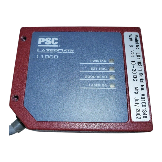
- Page 6 ® LazerData 11000 Series Bar Code Scanner Figure A. Top and Bottom External View Power ON/Data TX LED Warning and Device Class Labels Presence Sensor LED Accessory Mounting Holes Good Read LED Laser Beam Output Window Laser ON LED Mounting Holes...
-
Page 7: Safety Precautions
SAFETY PRECAUTIONS LASER SAFETY The following information is provided to comply with the rules imposed by ® international regulatory agencies and refers to the correct use of the LazerData 11000 Series Bar Code Scanner. Standard Regulations This scanner utilizes a low-power laser diode. Although staring directly at the laser beam momentarily causes no known biological damage, avoid staring at the beam as one would with any very strong light source, such as the sun. - Page 8 WARNING Use of controls or adjustments or performance of procedures other than those specified herein may result in exposure to hazardous visible laser light. The laser light is visible to the human eye and is emitted from the window on the front of the scanner (Figure A., Warning labels (Figure B.) indicating exposure to laser light and the device classification are applied onto the body of the scanner (Figure A.,...
- Page 9 The laser diode used in this device is classified as a class 3B laser product according to IEC 825-1 regulations and as a Class IIIb laser product according to CDRH regulations. As it is not possible to apply a classification label on the laser diode used in this device, the following label (Figure C.) is reproduced here.
-
Page 10: General Features
These were designed to satisfy demanding requirements associated with high performance scanning. C Programmability The LazerData 11000 Scanner belongs to the generation of PSC Automation scanners that operate under the 'C' programming environment, a recognized industry standard. -
Page 11: Description
® LazerData 11000 Scanner Installation Manual DESCRIPTION ® Some of the main features of the LazerData 11000 Scanner are — • small size • scanning speed of up to 600 scans/s • raster version availability • serial communication interfaces (one or two) •... -
Page 12: Available Models
® Installation Manual LazerData 11000 Scanner AVAILABLE MODELS The LazerData 11000 Scanner is available in models with variances in the following • Resolution • Interface module and cable termination • Linear or raster models • Performance The following models are available — L D 11 0 X 1 X R S 2 3 2 /R S 2 3 2 S td (3 5 0 s /s) ®... -
Page 13: Ld11-90 Deflection Mirror
® LazerData 11000 Scanner Installation Manual LD11-90 DEFLECTION MIRROR The LD11-90DEG Deflection Mirror is available on request for the LazerData 11000 Scanner. The installation of the LD11-90DEG Deflection Mirror is very easy (see Figure 1-1). CAUTION Avoid any contact with the deflection mirror, mirrored rotor, the lenses, or other optical components. -
Page 14: Installation
® Installation Manual LazerData 11000 Scanner INSTALLATION PACKAGE CONTENTS ® Verify that the LazerData 11000 Series Bar Code Scanner and all the parts supplied with the equipment are present and intact when opening the packaging. The list of parts includes: ®... -
Page 15: Guide To Installation
® LazerData 11000 Scanner Installation Manual GUIDE TO INSTALLATION The following can be used as a checklist to verify all of the steps necessary for ® complete installation of the LazerData 11000 Scanner. 1. Read all information in the section "Safety Precautions” at the beginning of this manual. -
Page 16: Mechanical Installation
® Installation Manual LazerData 11000 Scanner MECHANICAL INSTALLATION ® The LazerData 11000 Scanner can be installed to operate in different positions. The four screw holes (M4 x 5) on the body of the reader are for mechanical fixture (Figure A., ). -
Page 17: Electrical Connections
® LazerData 11000 Scanner Installation Manual ELECTRICAL CONNECTIONS ® Several LazerData 11000 Scanner models are equipped with a cable terminated by a 25-pin female D-sub connector for connection to the power supply and input/output signals. The details of the connector pins are indicated in the following table: Figure 2.3 - 25-pin female D-sub connector 25-pin D-sub connector pinout... -
Page 18: Power Supply
® Installation Manual LazerData 11000 Scanner Some scanner models are equipped with a 9-pin female connector. The details of the connector pins are indicated in the following table: Figure 2.4 - 9-pin female connector 9-pin connector pinout Name Function Power supply input voltage (+) Power supply input voltage (-) Presence sensor (+) Presence sensor (-) -
Page 19: Main Serial Interface
® LazerData 11000 Scanner Installation Manual 2.4.2 Main serial interface The signals relative to the following serial interface types are available on the input/output connector of the scanner depending on the scanner model (see section 1.3). If the interface type is not compatible with the current communication handshaking, then the system forces the XON/XOFF protocol. - Page 20 ® Installation Manual LazerData 11000 Scanner 11000 11000 USER INTERFACE scanner 9-pin scanner 25-pin TX232 TX232 RX232 RX232 RTS232 RTS232 CTS232 CTS232 SGND SGND SGND RTS/CTS HARDWARE HANDSHAKING ENABLED Figure 2.6 - RS232 main interface connections START OF START OF END OF TRANSMISSION TRANSMISSION...
-
Page 21: Rs485-Nonpolled Interface
® LazerData 11000 Scanner Installation Manual RS485-nonpolled interface The RS485-nonpolled interface is a Full Duplex interface. The nonpolled configuration is used for point-to-point connections over longer distances than those acceptable for RS232 communications or in electrically noisy environments. The following pins of the 25-pin connector are used for RS485-nonpolled communications: 25-Pin Name... -
Page 22: Rs485-Polled Interface
® Installation Manual LazerData 11000 Scanner RS485-polled interface The RS485-polled interface is a Half Duplex (3 wires + shield) interface. The polled configuration can be used for Multidrop connections with a Multiplexer, or it can be used for a master-slave layout (see section 2.6.1). The following pins of the 25-pin connector are used for RS485-polled communications: 25-Pin... - Page 23 ® LazerData 11000 Scanner Installation Manual ® The figure below shows a multidrop configuration with the LazerData 11000 Scanner connected to a Multiplexer. 120 Ohm max. 2 m. 6.6 ft. 11000 scanner (up to 31) 11000 scanner max. 1,200 m. TX485+ 1,312 yds.
-
Page 24: 20-Ma Current Loop Interface
® Installation Manual LazerData 11000 Scanner 20-mA current loop interface ® The LazerData 11000 Scanner only supports passive type current loop connections. The following pins of the 25-pin connector are used: 25-Pin Name Function CLIN- Current Loop Input (-) CLIN+ Current Loop Input (+) CLOUT- Current Loop Output (-) -
Page 25: Auxiliary Rs232 Interface
® LazerData 11000 Scanner Installation Manual 2.4.3 Auxiliary RS232 interface The auxiliary serial interface is used exclusively for RS232 point-to-point connections. The parameters relative to the aux interface (baud rate, data bits, etc.) as well as particular operating modes such as LOCAL ECHO can be defined using the LDHOST utility program or "Host Mode"... -
Page 26: Inputs
® Installation Manual LazerData 11000 Scanner 2.4.4 Inputs The inputs available on the connector supplied with the scanner are the pins relative to the code presence sensor, as indicated below: 9-Pin 25-Pin Name Function Presence sensor (input +) Presence sensor (input -) The inputs indicated are used to connect the code presence sensor, which tells the scanner to scan for a code. - Page 27 ® LazerData 11000 Scanner Installation Manual 11000 11000 PRESENCE SENSOR scanner 9-pin scanner 25-pin + 5V Signal Ground Figure 2.14 - Input NPN command using 11000 Scanner power Vext 30 VDC max. 11000 11000 PRESENCE SENSOR scanner 25-pin scanner 9-pin + 5V Signal Ground...
-
Page 28: Outputs
® Installation Manual LazerData 11000 Scanner 2.4.5 Outputs The outputs are available only on 25-pin connector models. The following pins are present on the 25-pin connector of the scanner: 25-Pin Name Function NO READ+ No read output (+) I/O REF- I/O reference RIGHT+ Right read output (+) -
Page 29: Positioning
® LazerData 11000 Scanner Installation Manual POSITIONING The LaserData® 11000 Scanner is able to decode moving bar code labels at a variety of angles. However, significant angular distortion may degrade reading performance. When mounting the scanner, take into consideration these three ideal label-position angles: Pitch 0°, Skew 10°... -
Page 30: Typical Layouts
® Installation Manual LazerData 11000 Scanner The Tilt angle is represented by the angle T in Figure 2.20. Position the reader in order to minimize the Tilt angle. 11000 scanner Figure 2.20 - Tilt angle TYPICAL LAYOUTS When an object – bearing a bar code label – enters the scanner’s reading zone, a photoelectric sensor senses the presence of the symbol and activates the scanner. -
Page 31: Master-Slave
® LazerData 11000 Scanner Installation Manual 2.6.1 Master-slave The master-slave connection is used to collect data from several scanners to build a multisided reading system. There can be one master and up to 5 slaves connected with the RS485–polled mode on the main serial interface. The master scanner is also connected to a host PC with the RS232 auxiliary interface. -
Page 32: Local Echo
® Installation Manual LazerData 11000 Scanner 2.6.2 Local echo In Local Echo mode the data is transmitted on both the Auxiliary interface and on the Main interface. Host Mode programming can be accomplished either through the Main interface or the Auxiliary interface in Local Echo mode. Terminal 11000 scanner... -
Page 33: Pass Through
® LazerData 11000 Scanner Installation Manual 2.6.3 Pass Through Pass Through mode allows two or more devices to be connected to a single external serial interface. Each 11000 Scanner transmits the messages received by the auxiliary interface onto the main interface. All messages will be passed through this chain to the host. -
Page 34: Reading Features
® Installation Manual LazerData 11000 Scanner READING FEATURES The number of scans performed on the code by the scanner – and, therefore, the decoding capability – is influenced by the following factors: • number of scans per second • code motion speed •... -
Page 35: Picket Fence Mode
® LazerData 11000 Scanner Installation Manual For example, the 11000 Scanner (scanning at 350 scans/s) for a 25-mm high code moving at 500 mm/s performs: SN = [(25/500) * 350] - 2 = 15 effective scans. PICKET FENCE MODE Code motion direction at LS speed 11000 Laser Beam... -
Page 36: Performance
(12-inch) distance. If standard devices do not satisfy your specific requirements, send a representative code sample of your labels to the nearest PSC Automation distributor, who will in turn supply you with complete information on the reading possibilities. Reading Features - 3.3... -
Page 37: Reading Diagrams
® LazerData 11000 Scanner Installation Manual READING DIAGRAMS LD-11011X or -11031X (Standard Resolution, 350 scans/s) NOTE: (0,0) IS THE CENTER OF THE LASER BEAM OUTPUT WINDOW 12 in. code code 12 mil 20 mil 24 mil code 32 mil 8 mil 39 mil CONDITIONS: Code... - Page 38 ® Installation Manual LazerData 11000 Scanner LD-11021X or -11051X (High resolution, 350 scans/s) NOTE: (0,0) IS THE CENTER OF THE LASER BEAM OUTPUT WINDOW 5 in. code 12 mil code 6 mil code 8 mil CONDITIONS: Code = Interleaved 2/5 or Code 39 = 0.90 "Pitch"...
- Page 39 ® LazerData 11000 Scanner Installation Manual LD-11011X or -11031X (Standard resolution, 600 scans/s) NOTE: (0,0) IS THE CENTER OF THE LASER BEAM OUTPUT WINDOW 12 in. code code 20 mil code 12 mil 24 mil 8 mil 32 mil 39 mil code 12 mil code...
- Page 40 ® Installation Manual LazerData 11000 Scanner LD-11021X or -11051X (High resolution, 600 scans/s) NOTE: (0,0) IS THE CENTER OF THE LASER BEAM OUTPUT WINDOW 5 in. code 8 mil code 4 mil code 6 mil CONDITIONS: Code = Interleaved 2/5 or Code 39 = 0.90 "Pitch"...
- Page 41 ® LazerData 11000 Scanner Installation Manual 3.8 - Reading Features...
-
Page 42: Maintenance
® Installation Manual LazerData 11000 Scanner MAINTENANCE CLEANING Clean the laser beam output window periodically for continued optimal scanner operation. Dust, dirt, etc. on the window may alter the reading performance. Repeat the cleaning operation frequently in particularly dirty environments. Use a soft cloth material and alcohol to clean the window. - Page 43 ® LazerData 11000 Scanner Installation Manual 4.2 - Maintenance...
-
Page 44: Service And Warranty
NOT COVERED IN THIS WARRANTY. Service requests due to abuse, neglect, changes in original specifications, or service calls not related to the PSC equipment, will be charged at the current service rate and will include all travel-related expenses. Warranty coverage lasts for 12 months. - Page 45 ® LazerData 11000 Scanner PSC Automation, Inc. 5.2 - Service and Warranty...
-
Page 46: Technical Features
® Installation Manual LazerData 11000 Scanner TECHNICAL FEATURES ELECTRICAL FEATURES INPUT POWER Supply voltage 10 to 30 VDC Power consumption max. SERIAL INTERFACES (depends on model) MAIN RS232; RS485, Polled/NonPolled; 20 mA C.L. AUXILIARY RS232 BAUD All Interfaces 150 to 19200 CONTROL INPUTS PRESENCE SENSOR (opto-coupled NPN or PNP) - Page 47 ® LazerData 11000 Scanner Installation Manual SOFTWARE FEATURES READABLE CODE SYMBOLOGIES Up to 22 readable bar code symbologies, including: • EAN/UPC (including Add-on 2 and Add-on 5) • Code 93 • 2/5 Interleaved • Code 128 • Code 39 (Standard and Full ASCII) •...
- Page 48 Australia Hong Kong Spain PSC Asia Pacific Pty Ltd PSC Hong Kong PSC S.A.R.L. Sucursal en España Tel [61] 0 (2) 9878 8999 Fax [61] 0 (2) 9878 8688 Tel [852]-2-584-6210 Belgium Fax [852]-2-521-0291 Tel [34] 9 (1) 656 7525...
Need help?
Do you have a question about the LazerData 11000 Series and is the answer not in the manual?
Questions and answers