
Subscribe to Our Youtube Channel
Related Manuals for Tegam 1830A


Summary of Contents for Tegam 1830A
- Page 1 1830A RF Power Meter for Metrology Instruction and Service Manual PN# 1830A-901-01 Publication Date: October 2019 REV. N 10 TEGAM WAY • GENEVA, OHIO 44041 440-466-6100 • FAX 440-466-6110 • www.tegam.com...
- Page 2 Electro-Scientific Industries (ESI), Gertsch, Keithley Instruments, Lucas Weinschel, and Pragmatic Instruments. A complete list can be viewed on our Product Service Directory at www.tegam.com For more information about TEGAM and our products, please visit our website at www.tegam.com: or contact one of our customer service representatives at sales@tegam.com or 800-666-1010.
-
Page 3: Table Of Contents
…………………….……………….…. 4-17 1830A Commands ..............4-21 1830A Error/Status Reporting ..........4-23 Sensor Calibration File Upload ..........4-32 Heater Circuit Operation ............4-34 Normal Shutdown Procedure ............ 4-35 10 TEGAM WAY • GENEVA, OHIO 44041 440-466-6100 • FAX 440-466-6110 • www.tegam.com... - Page 4 Memory Sanitization Procedure ........... 6-2 VII. Preparation for Shipment Returning Power Meter for Service ..........7-1 Package Power Meter for Shipment ..........7-1 VIII. Storage Storage Requirement ..............8-1 10 TEGAM WAY • GENEVA, OHIO 44041 440-466-6100 • FAX 440-466-6110 • www.tegam.com...
- Page 5 As Marked on Equipment: CAUTION – Risk of Danger DANGER – Risk of Electric Shock Earth Ground Terminal Frame or Chassis Terminal Earth Ground Terminal Alternating Current 10 TEGAM WAY • GENEVA, OHIO 44041 440-466-6100 • FAX 440-466-6110 • www.tegam.com...
-
Page 6: Introduction
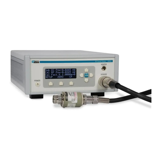
Section I – Introduction Purpose and Function The 1830A power meter is designed for thermistor based RF power sensors which are universally recognized as the most accurate means to measure and transfer RF power. The TEGAM Model 1830A is designed to replace the HP432 while further reducing uncertainties and accommodate a wider variety of RF power sensors. -
Page 7: Specifications
36.5 cm (14.5 in) Table 1.1 Physical and Electrical Specifications Please note that the Celsius scale specifications are controlling, the Fahrenheit conversions are approximations for information only. 10 TEGAM WAY • GENEVA, OHIO 44041 440-466-6100 • FAX 440-466-6110 • www.tegam.com... - Page 8 Line Voltage Selection The power supply in a Model 1830A operates with a line voltage of 100 to 240 VAC at 48 to 62 Hz. CAUTION DO NOT APPLY POWER TO THE INSTRUMENT BEFORE READING THIS SECTION.
-
Page 9: List Of Items Furnished
Table 1.3 - 1830A Accessory List Tools and Test Equipment No special tools and test equipment are needed to operate the 1830A. The follow is a list of thermistor mounts that will operate with the 1830A RF Power Meter. 478A, 8478B, S486A, G486A, J486A, H486A,... -
Page 10: Preparation For Calibration Or Repair Service
Section I – Introduction Preparation for Calibration or Repair Service Once you have verified that the cause for 1830A malfunction cannot be solved in the field and the need for repair and calibration service arises, contact TEGAM customer service to obtain an RMA, (Returned Material Authorization), number. - Page 11 Include information such as measurement range, instrument settings, type of components being tested, is the problem intermittent? When is the problem most frequent? Has anything changed with the application since the last time the instrument was used?, etc. 10 TEGAM WAY • GENEVA, OHIO 44041 440-466-6100 • FAX 440-466-6110 • www.tegam.com...
-
Page 12: Warranty Information
TEGAM service center with shipping charges prepaid. TEGAM Inc. shall pay for the return of the product to the customer if the shipment is to a location within the country in which the TEGAM service center is located. The customer shall be responsible for paying all shipping, duties, taxes, and additional costs if the product is transported to any other locations. -
Page 13: Preparation For Use And Installation
Do Not Block Air Vents on Rear Panel CAUTION The Model 1830A has an air intake and exhaust on the back panel of the instrument. When installing the Model 1830A, ensure there is at least two inches of space behind the instrument for airflow. -
Page 14: Principles Of Operation
The Model 1830A RF Power Meter combines a DC substitution balancer with a digital voltmeter system. The use of a A/D converter converts our analog measurement to a digital output on the 1830A front panel. This eliminates the need for any type of analog output that an instrument like the Agilent 432A may require. -
Page 15: Theory Of Rf Power Measurements
DC substitution is the key for precise RF power measurements. The Model 1830A uses the principle of DC substitution to measure RF power. DC substitution refers to the measurement of RF power according to the amount of DC power that must be substituted for the RF power in a bolometer in order to cause equivalent thermal effects. -
Page 16: Controlling Thermistor Temperature
The servo amplifier controls the main supply transistor and therefore regulates power to the combined reference/bolometer circuit. The Model 1830A is designed to support NTC devices. When the bolometer voltage is higher than desired, power is increased to heat the bolometer to decrease resistance. When the bolometer voltage is lower than the reference resistor voltage, power is decreased. -
Page 17: Start-Up Procedure
After unpacking the 1830A and setting up in the proper operating environment, plug in the AC power cord. Do not connect any cables at this point. Press the POWER button located on the lower left side of the 1830A. When the 1830A finishes the power on cycle, it will power into Standby Mode. -
Page 18: Connecting The Proper Sensor
Section IV– Operating Instructions Connecting the Proper Sensor There are many thermistor based RF power sensors available. The Model 1830A is designed to bias either 100 Ω or 200 Ω mounts and has dual bridges for balancing both RF sense and compensation thermistors such as contained in the Agilent 478A and 8478B. It also is works with the Agilent 486A series of waveguide sensors and includes a heater circuit for all TEGAM and Weinschel ovenized thermistor mounts. -
Page 19: 1830A Front Panel Menus
4. Maintenance Figure 4.4 SETUP Menu Standby Mode (Write Only) Standby is explained above, it is available in the SETUP menu, also the 1830A will power up in standby mode every time. Instrument Menu Located in the SETUP menus where all measurement related parameters are set. The Instrument menu contains 11 selections. - Page 20 • 432 Bias Comp No Compensation – To be used with TEGAM thermistor mounts such as the F1130A. The TEGAM thermistor mount is a type of bolometer whose resistance decreases as a function of increasing heat associated with ambient temperature or applied power. This system also features the Model 1830A temperature control circuitry that temperature stabilizes TEGAM and Weinschel thermistor mounts.
- Page 21 Network Options Located SETUP—Instrument menu. Configure the 1830A remote communication via TCP/IP. The 1830A is controlled via TCP/IP through an Ethernet cable connection. Transmission Control Protocol/Internet Protocol (TCP/IP) is the most popular network protocol and the basis for the Internet. Its routing capabilities provide maximum flexibility in an enterprise-wide network.
- Page 22 Access Control protocol sub-layer. Network Link Activity (Read Only): Located SETUP—Instrument—Network Options menu. This indicator tells you if your network link is active or if there is a fault. 10 TEGAM WAY • GENEVA, OHIO 44041 440-466-6100 • FAX 440-466-6110 • www.tegam.com...
- Page 23 An example of this would be a laptop PC, if the wireless is being used for network communication the 1830A can be plugged into the wired connection and establish a link only with the laptop. A similar scenario can also be established with two network cards.
- Page 24 Analog Board Firmware Version (Read Only) Located SETUP—Instrument—Analog Brd FW Ver menu. This indicates the current firmware version and firmware date for the analog board on the 1830A. Auto Scale Reading (Read/Write) Located SETUP—Instrument—Auto Scale Reading menu. This control is defaulted to False, all power reading will be displayed in mW.
- Page 25 8. Cal Limits Debug Level (Read Only) Located SETUP—Maintenance menu. This indicator is used to tell the TEGAM developer a digital code that represents a debug level. This indicator is used for development and is not useful to the end user.
- Page 26 The connectors are Type “A”: a standard A-A USB cable can be used to connect the 1830A to a PC (TEGAM Part Number CA-14-2M). The 1830A will enumerate to Microsoft Windows as a serial port. Therefore, software may interface with the 1830A using simple serial port calls.
- Page 27 Cal Warning (Yellow) – Defaulted to 75% • Cal Fail (Red) – Defaulted to 100% NOTE Follow Figure 4.4 in this section to configure the USB port for communication. 10 TEGAM WAY • GENEVA, OHIO 44041 440-466-6100 • FAX 440-466-6110 • www.tegam.com 4-11...
-
Page 28: 1830A Menu Map
Section IV– Operating Instructions 1830A Menus Map Figure 4.5 - Front Panel Menu Map 10 TEGAM WAY • GENEVA, OHIO 44041 440-466-6100 • FAX 440-466-6110 • www.tegam.com 4-12... -
Page 29: Normal Operation
The 1830A itself will warm up in approximately one hour, depending on airflow conditions. Please refer to bolometer’s manual for warm-up time. Allow the reading from the 1830A to settle before recording a reading. In most conditions, a few seconds after applying RF is adequate. - Page 30 2. Using the CF (Calibration Factor) soft-key enter the calibration factor for the desired frequency. 3. Using the ZERO soft-key, ZERO the 1830A. (This may take a few seconds) 4. Turn RF OUTPUT “ON” on the RF Signal Generator 5. Read calibrated power from the front panel of the Model 1830A 10 TEGAM WAY •...
-
Page 31: Remote Operation
The LAN interface is only available through the TCP/IP Connection. Refer to Figure 4.1 for location of remote interfaces. Figure 4.6 - Rear Panel Connections 10 TEGAM WAY • GENEVA, OHIO 44041 440-466-6100 • FAX 440-466-6110 • www.tegam.com 4-15... - Page 32 Navigate to the 1830A resources page and download the 1830A USB driver. • Using CA-14-2M connect the 1830A using the lower USB port to the PC that will be used to control the 1830A. • Use the flow chart in Figure 4-3 to set the 1830A for USB-Serial communication.
-
Page 33: Ethernet Interface Configuration
IP address. If you connect the 1830A to the network after it's already turned on, the instrument will request an IP address at that time. - Page 34 Connecting to the Ethernet port of a PC Another way to connect to the 1830A to a PC is to simply connect the Ethernet port of the 1830A directly to the Ethernet port of a PC. To do this, you'll have to configure the 1830A to be in Automatic IP Addr mode as described above.
- Page 35 Instrument -> Network Options -> IP Address from the front panel. If you have typed in the correct IP address, the 1830A will display its home page as shown in Figure 4.9. At this point, a limited amount of functions are available until you log in.
- Page 36 Figure 4.10. The default password is “admin.” Figure 4.10 - 1830A LAN interface Login If you have entered the correct password, the 1830A will display the page shown in Figure 4.11. From this screen, much more information and functionality is available to the user.
-
Page 37: 1830A Commands
Section IV– Operating Instructions 1830A Commands The 1830A can be accessed through a USB interface (as a serial port), or through the LAN interface Web page (TCP/IP). In either case, you can send commands to the 1830 to read the value of variables, including instrument settings and measurement values, or change settings. - Page 38 If the command was successful, the 1830A will return the string: 00:0.9500 VARIABLE LIST Command This command displays a list of all of the 1830A system variables. VARIABLE CONFIG Command This command displays a list of all static system variables and their current values. It returns a string that can be used to back up the system.
-
Page 39: 1830A Error/Status Reporting
Section IV– Operating Instructions 1830A Error/Status Reporting A status is returned from the 1830A after each command. Each status, or error code, is comprised of two digits followed by a colon. (i.e. 12:). The error code indicates if there was problem with the command. - Page 40 Update the K Factor value for a specific sensor Table 4.2 - Model 1830A Sensor Commands Front Panel Commands These commands are used emulate the front panel of the 1830A. These commands would be used if not directly in front of the device or external application automation. Command...
- Page 41 Dac Voltage Counts DAC_Z_F_1 Dac Voltage AIN_RV_FINE_Z_1 Ref. Volt Fine Zero Cnts AIN_RV_FINE_Z_F_1 Ref. Volt Fine Zero AIN_RV_FINE_1 Ref. Volt Fine Cnts AIN_RV_FINE_F_1 Ref. Volt Fine 10 TEGAM WAY • GENEVA, OHIO 44041 440-466-6100 • FAX 440-466-6110 • www.tegam.com 4-25...
- Page 42 100 Ohm Channel Calcd AB_100_RESISTANCE_1_OLD Resistance 200 Ohm Channel Calcd AB_200_RESISTANCE_1_OLD Resistance Custom Resistor Channel Gain AB_RESISTANCE_GAIN_1_OLD Setting Custom Resistor Channel Offset AB_RESISTANCE_OFFSET_1_OLD Setting AB_BV_DAC_2 BV DAC Setting 10 TEGAM WAY • GENEVA, OHIO 44041 440-466-6100 • FAX 440-466-6110 • www.tegam.com 4-26...
- Page 43 Substituted Power * K Cal Factor DAC_Z_2 Dac Voltage Counts DAC_Z_F_2 Dac Voltage AIN_RV_FINE_Z_2 Ref. Volt Fine Zero Cnts AIN_RV_FINE_Z_F_2 Ref. Volt Fine Zero AIN_RV_FINE_2 Ref. Volt Fine Cnts 10 TEGAM WAY • GENEVA, OHIO 44041 440-466-6100 • FAX 440-466-6110 • www.tegam.com 4-27...
- Page 44 DAC RV Channel Low Gain AB_DAC_RV_LOW_GAIN_1 Setting DAC RV Channel Low Offset AB_DAC_RV_LOW_OFFSET_1 Setting DAC RV Channel Low Gain AB_DAC_RV_LOW_GAIN_2 Setting DAC RV Channel Low Offset AB_DAC_RV_LOW_OFFSET_2 Setting 10 TEGAM WAY • GENEVA, OHIO 44041 440-466-6100 • FAX 440-466-6110 • www.tegam.com 4-28...
- Page 45 BALANCE_VOLTAGE_2 Balance Voltage ENABLE_OPEN_WIRE_DETECT Enable Open Wire Detection NETWORK_ENABLED Network Enable READING_AVERAGES Reading Averages Table 4.4 - List of SET and GET Variables for the 1830A 10 TEGAM WAY • GENEVA, OHIO 44041 440-466-6100 • FAX 440-466-6110 • www.tegam.com 4-29...
- Page 46 The password used to login to the system is invalid System Is Locked The system is currently locked to all access by another user Sensor Serial Number Length Too Long 10 TEGAM WAY • GENEVA, OHIO 44041 440-466-6100 • FAX 440-466-6110 • www.tegam.com 4-30...
- Page 47 System in Standby System is zeroing Lock Failed Fork Failed Fork Application Failed Bad File Invalid calibration OWD Check in Process Table 4-5 - Error Codes 10 TEGAM WAY • GENEVA, OHIO 44041 440-466-6100 • FAX 440-466-6110 • www.tegam.com 4-31...
-
Page 48: Sensor Calibration File Upload
Section IV– Operating Instructions Sensor Calibration File Upload The 1830A allows users to upload sensor calibration data for multiple sensors at one time through the LAN interface. NOTE: A file size of 5000 rows in excel was tested for this document. Tins will allow for 25 sensors with 200 data points each. - Page 49 Navigate to Sensor Data page. • Browse to the file created and upload file. (This may take several seconds depending on file size) Figure 4.15 - Upload Sensor Data File 10 TEGAM WAY • GENEVA, OHIO 44041 440-466-6100 • FAX 440-466-6110 • www.tegam.com 4-33...
-
Page 50: Heater Circuit Operation
0.6 Volts. If the 1830A front panel heater status indicator does not change to ‘Htr OK’ after a 2 hour warm up, the selected step size may be too large. A very small number of thermistor mounts may enter regulation with a voltage that is less than 0.6 V below the... -
Page 51: Normal Shutdown Procedure
Normal Shutdown Procedure Press the power button will start the normal shut down procedure. Shutdown will take several seconds to insure proper shutdown has occurred. Do not unplug the 1830A until the LCD goes black and fan stop indicating shutdown is com 10 TEGAM WAY •... -
Page 52: Maintenance And Servicing
Section V – Maintenance and Servicing 1830A System Calibration and Diagnostics The calibration of the 1830A is a web based process and requires a LAN connection. Please refer to Section IV of this manual for instructions on how to make a LAN connection. -
Page 53: Calibration Environment
Section V – Maintenance and Servicing Calibration Environment Calibration and verification should be performed in laboratory operating conditions as stated in Section I; Table 1.1. Allow 1830A to warm up for at least one hour before calibration. Disassembly of 1830A There is no disassembly required for calibration of the 1830A. - Page 54 Section IV (Operating Instructions). Select System Calibration from the LAN interface web menu (Refer to Figure 5.1). Select Engineering Diagnostics/Verification. Figure 5.1 - System Calibration Webpage (Diagnostics) 10 TEGAM WAY • GENEVA, OHIO 44041 440-466-6100 • FAX 440-466-6110 • www.tegam.com...
- Page 55 Channel 1 or Channel 2 (Refer to Figure 5.2). Diagnostics gives individual channel control that is not available in the full calibration. Figure 5.2 - Diagnostic Channel Selection 10 TEGAM WAY • GENEVA, OHIO 44041 440-466-6100 • FAX 440-466-6110 • www.tegam.com...
- Page 56 Refer to figures 5.4 & 5.5 for an example of what these screens contain. Figure 5.3 - Diagnostic Operation Selection Figure 5.4 – Zero Servo Loop 10 TEGAM WAY • GENEVA, OHIO 44041 440-466-6100 • FAX 440-466-6110 • www.tegam.com...
- Page 57 Note: Each calibration and diagnostic step allows the user to view a connection diagram. Figure 5.5 is an example of the diagram. This manual will not contain all the connection diagrams because they are available on the LAN interface webpage. 10 TEGAM WAY • GENEVA, OHIO 44041 440-466-6100 • FAX 440-466-6110 • www.tegam.com...
- Page 58 Section V – Maintenance and Servicing Figure 5.5 – Zero Servo Loop Connection Example Schematic 10 TEGAM WAY • GENEVA, OHIO 44041 440-466-6100 • FAX 440-466-6110 • www.tegam.com...
- Page 59 Figure 5.7 for the first step in the calibration. Detailed procedures and diagrams will be provided for each step of the calibration (Refer to Figures 5.4 & 5.5). 10 TEGAM WAY • GENEVA, OHIO 44041 440-466-6100 • FAX 440-466-6110 • www.tegam.com...
- Page 60 WARNING Once calibration is complete the user will be asked to save data. If the user chooses not to save the new data, all new calibration data will be lost. 10 TEGAM WAY • GENEVA, OHIO 44041 440-466-6100 • FAX 440-466-6110 • www.tegam.com...
-
Page 61: Troubleshooting
Section V – Maintenance and Servicing Troubleshooting The 1830A is designed to be calibrated and verified without removing the cover or any other disassembly. However there may a time when the 1830A is not operate correctly or within specifications. Check the Basics Before calling TEGAM or returning the power meter for service, please make the following checks. - Page 62 • Verify correct compensation mode is selected. • Problem: I am getting a voltage error on channel 2 causing the 1830A to enter Standby mode. Solution: Verify 1830A is connected to a sensor. • Verify sensor cable is fully connected to the 1830A and the sensor.
-
Page 63: Reprogramming
2Meg in size cannot be uploaded. The upgrade stops the 1830A webserver for a few seconds, so give the upgrade a little time to happen. Please note the web browser may show a time out or connection error. This is normal as the unit needs to restart its internal web server to apply the fixes. -
Page 64: Memory Sanitization Procedure
TEGAM to restore 1830A to a usable condition. Method 1 - If the firmware version is v1.1.50a or higher there is not an SD card in your 1830A and you would follow the following steps. -
Page 65: Preparation For Shipment
Section VII – Preparation for Shipment Returning Power Meter for Service Use the information in this section if you need to return your power meter to TEGAM. Package Power Meter for Shipment Use the following steps to package the power meter for shipment to TEGAM for service: Fill the EXPEDITE REPAIR &... -
Page 66: Storage Requirement
Section VIII – Storage Storage Requirements When the Model 1830A is to be stored for extended periods, pack the instrument into a container. Place container in a clean, dry, temperature-controlled location. If instrument is to be stored in excess of 90 days, place desiccant with items before sealing container.
Need help?
Do you have a question about the 1830A and is the answer not in the manual?
Questions and answers