
Subscribe to Our Youtube Channel
Related Manuals for Apollo Mini Series


Summary of Contents for Apollo Mini Series
- Page 1 Mini RADIO REMOTE CONTROL HANDBOOK AC version Please read the handbook carefully before operation to avoid any dangerous or damage may be incurred Nov 2012...
-
Page 3: Table Of Contents
Mini INTRODUCTION TABLE Of CONTENTS 1. Introduction ........................2 1.1 Features ........................2 2. Models..........................2 3. Transmitter .........................2 3.1 Technical data......................2 3.2 Indicator ........................3 3.3 Power on steps .....................3 3.4 Power off steps .....................3 3.5 Standard mini butt on layout .................3 4. -
Page 4: Introduction
Mini 1. INTRODUCTION INTRODUCTION 1.1 FEATURES: 1. Pocket-size transmitter, light ,more handy for operation. 2. Advance program design, quick & good performance on movements. 3. ABS +PC transmitter housing, water/shock/dust proof. 4. Single-low button transmitter, compact and lighter design, ensure safe & convenient operation . 5. -
Page 5: Indicator
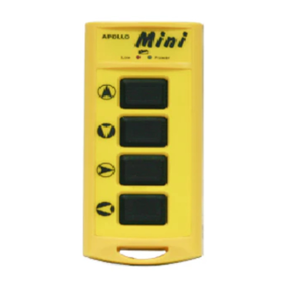
Mini 3.2 INDICATOR: RED/GREEN both indicators are NOT lighting ( EMS ON ) stand-by ( power on ) operation GREEN indicator light blinking power low RED indicator light blinking ( when button pressed ) power off Indicator lights off ( EMS OFF ) EMS stop 3.3 POWER-ON STEPS: ( 1 ) Power on receiver. -
Page 6: Receiver
Mini 4. RECEIVER 4.1 TECHNICAL DATA: Frequency : FM 418/433Mhz Sensitivity of RF:-110dBm Antenna : internal type Operation Temperature : -10 C~+75 C Source Voltage: 110/220/380/415VAC,50/60Hz Enclosure: IP67 Consumption: <12W Security Code: 256sets Weight: 560g ( Including the 8 core cable, 2m ) protection: short protection Color: Grey BOX 1.1... -
Page 7: Installation Notes
Mini 4.3 INSTALLATION NOTES: Dimension of receiver ( 1 ) Ensure the original wired control of equipment works. ( 2 ) Shut down equipment main power source before installation. ( 3 ) Mount in a firmed site where the receiver can be seen easily by operator. -
Page 8: Trouble Shooting-Tx
Mini 5. TROUBLE SHOOTING- TX Please make sure the following status before trouble shooting. ( 1 ) The hoist or device is subject to control works ( 2 ) The TX outlook is in good condition without leakage ( 3 ) Receiver works Power LED is LED NOT light or If working after... -
Page 9: Parts List
Mini 7. PARTS LIST SPARE PARTS TRANSMITTER RECEIVER part number part number description description part number part number description description trasmitter casing (incl. RED stop, receiver housing incl. cable gland BOX1.1 rubber pushbuttons,battery case ) MDD-20-A decoder board ( Mini 20 ) encoder board( Mini 20 ) MED-20 MDD-30-A... - Page 10 Mini Ensure your safety is our responsibility, use the remote control with the value is more than its worth is your right. Mini Standard circuit illustration. APOLLO mini 20C APOLLO mini 30C APOLLO mini 40C APOLLO mini 60C...
- Page 11 Mini Installation Wiring Diagram APOLLO mini 20C Decoder & Relay Board Indicator Wires Location in Decoder & Relay Board ( front side ) COMMON HF board function kit fuse Adapter FUSE 5A COMMON POWER FUSE 2A POWER F1 2A Power Fuse...
- Page 12 Mini Installation Wiring Diagram APOLLO mini 30C Decoder & Relay Board Indicator Wires Location in Decoder & Relay Board ( front side ) COMMON COMMON HF board function kit fuse Adapter FUSE 5A COMMON POWER FUSE 2A POWER F1 2A Power Fuse...
- Page 13 Mini Installation Wiring Diagram APOLLO mini 40C Decoder & Relay Board Indicator Wires Location in Decoder & Relay Board ( front side ) COMMON COMMON HF board function kit fuse Adapter FUSE 5A COMMON POWER FUSE 2A POWER F1 2A Power Fuse...
- Page 14 Mini Installation Wiring Diagram APOLLO mini 60C Decoder & Relay Board Indicator Wires Location in Decoder & Relay Board ( front side ) COMMON COMMON COMMON HF board function kit fuse Adapter FUSE 5A COMMON POWER FUSE 2A POWER F1 2A Power Fuse...
-
Page 15: Warranty
WARRANTY The equipment is warranted for one year from date of purchase against defects in materials or workmanship provided it was purchased from 3-Elite or authorized dealer. This warranty does not cover equipment which has been abused or damaged by careless handling or shipping, OR damaged by nature disaster such as earthquake, typhoon etc. - Page 16 STANDARD ACCESSORY receiver x 1 transmitter x 1 handbook x 1 transmitter sleeve x 2 Nylon belt for transmitter x 1 screw x 4...
Need help?
Do you have a question about the Mini Series and is the answer not in the manual?
Questions and answers